AXLE AND DIFFERENTIAL REAR AXLE CARRIER REMOVAL
CAUTION / NOTICE / HINT
The necessary procedures (adjustment, calibration, initialization, or registration) that must be performed after parts are removed and installed, or replaced during rear axle carrier sub-assembly removal/ installation are shown below.
- HINT:
- ·
Use the same procedure for the RH side and LH side.
·The following procedure is for the LH side.
| Replacement Part or Procedure | Necessary Procedure | Effect/Inoperative when not Performed | Link |
|---|---|---|---|
| Front wheel alignment adjustment | Calibration | ·
DTCs are stored ·
Slip indicator light illuminates ·
VSC disabled or malfunctions |
( ) |
PROCEDURE

 1.REMOVE REAR WHEEL
42312B
2.REMOVE REAR AXLE SHAFT NUT
3.SEPARATE REAR DISC BRAKE CALIPER ASSEMBLY
42491
4.REMOVE PARKING BRAKE SHOE ADJUSTING HOLE PLUG
42431
5.REMOVE REAR DISC
89546
6.DISCONNECT REAR SPEED SENSOR
42450B
7.REMOVE REAR AXLE HUB AND BEARING ASSEMBLY
8.REMOVE REAR BRAKE
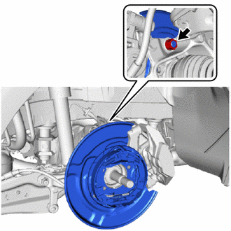
Remove the nut and rear brake from the rear axle carrier sub-assembly.
9.REMOVE FLEXIBLE HOSE BRACKET
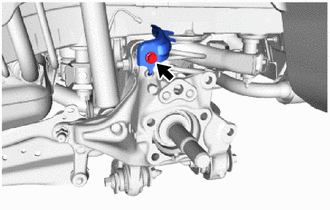
Remove the bolt and flexible hose bracket from the rear axle carrier sub-assembly.
48840A
10.REMOVE REAR STABILIZER LINK ASSEMBLY
48231B
11.REMOVE REAR COIL SPRING
48258C
12.REMOVE REAR LOWER COIL SPRING INSULATOR
48720A
13.REMOVE REAR NO. 1 SUSPENSION ARM ASSEMBLY
14.REMOVE REAR AXLE CARRIER SUB-ASSEMBLY
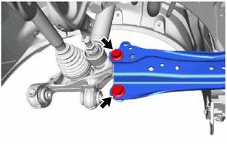
Loosen the 2 bolts of the rear trailing arm assembly.
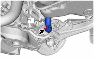
| *1 | Rear Axle Carrier Pin |
Loosen the nut of the rear shock absorber assembly.
- NOTICE:
-
Hold the rear axle carrier pin while rotating the nut.
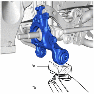
| *a | Wooden Block |
| *b | Jack |
Using a jack and a wooden block, support the rear axle carrier sub-assembly.
- NOTICE:
- ·
When jacking up the rear axle carrier sub-assembly, be sure to jack it up slowly.
·Make sure to perform this operation with the vehicle kept as low as possible.
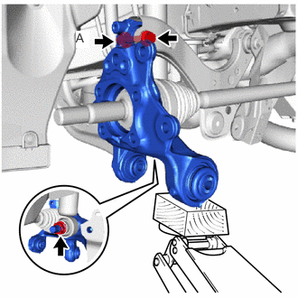
Loosen the bolt (A).
- NOTICE:
-
Loosen the bolt with the nut secured.
Remove the 2 bolts and separate the rear trailing arm assembly from the rear axle carrier sub-assembly.
Remove the nut and separate the rear shock absorber assembly from the rear axle carrier sub-assembly.
- NOTICE:
-
Hold the rear axle carrier pin while rotating the nut.
Remove the bolt (A), nut and rear axle carrier sub-assembly from the rear upper control arm assembly.
- NOTICE:
-
Loosen the bolt with the nut secured.