NETWORKING NETWORK GATEWAY ECU(for LHD) INSTALLATION
CAUTION / NOTICE / HINT
- NOTICE:
-
After performing the update ECU security key procedure, make sure to perform the initialization procedure for when the cable has been disconnected and reconnected to the negative (-) auxiliary battery terminal.
PROCEDURE

 89111
1.INSTALL CENTRAL GATEWAY ECU (NETWORK GATEWAY ECU)
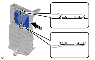

|
Install in this Direction |
Engage the claws to install the central gateway ECU (network gateway ECU) as shown in the illustration.
- NOTICE:
-
Make sure that the central gateway ECU (network gateway ECU) is securely installed.
82878
2.INSTALL ECU INTEGRATION BOX RH
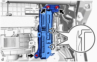
Engage the claws to install the ECU integration box RH.
Install the bolt and 2 nuts.
- Torque:
- 8.0 N*m (82 kgf*cm, 71 in.*lbf)
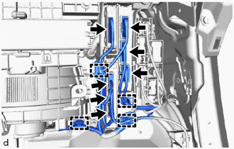
Connect the 7 connectors and engage the clamps.
55433B
3.INSTALL LOWER NO. 2 INSTRUMENT PANEL FINISH PANEL
55550
4.INSTALL GLOVE COMPARTMENT DOOR ASSEMBLY
55317E
5.INSTALL NO. 1 INSTRUMENT SIDE PANEL
62311B
6.CONNECT FRONT DOOR OPENING TRIM WEATHERSTRIP RH
- HINT:
-
Use the same procedure as for the LH side.
-
Click hereVehicle Interior>INTERIOR PANELS / TRIM>INSTRUMENT PANEL SAFETY PAD>INSTALLATION
55607
7.INSTALL NO. 2 INSTRUMENT PANEL UNDER COVER SUB-ASSEMBLY
62111C
8.INSTALL COWL SIDE TRIM BOARD RH
- HINT:
-
Use the same procedure as for the LH side.
-
Click hereVehicle Interior>INTERIOR PANELS / TRIM>ROOF HEADLINING (for 5 Door)>INSTALLATION
67913B
9.INSTALL FRONT DOOR SCUFF PLATE RH
- HINT:
-
Use the same procedure as for the LH side.
-
Click hereVehicle Interior>INTERIOR PANELS / TRIM>ROOF HEADLINING (for 5 Door)>INSTALLATION
58810J
10.INSTALL FRONT CONSOLE BOX SUB-ASSEMBLY (for 5 Door)
58810J
11.INSTALL CONSOLE BOX ASSEMBLY (for 3 Door)
33554
12.INSTALL SHIFT LEVER CAP (for CVT)
33504F
13.INSTALL SHIFT LEVER KNOB SUB-ASSEMBLY (for CVT)
33504F
14.INSTALL SHIFT LEVER KNOB SUB-ASSEMBLY (for Manual Transaxle)
55407B
15.INSTALL SWITCH HOLE BASE SUB-ASSEMBLY
55432B
16.INSTALL LOWER INSTRUMENT PANEL FINISH PANEL
55479E
17.INSTALL LOWER INSTRUMENT CLUSTER FINISH PANEL GARNISH
18.CONNECT CABLE TO NEGATIVE AUXILIARY BATTERY TERMINAL
for 1KR-FE:
Click hereGeneral>MAINTENANCE>1KR-FE AUXILIARY BATTERY>INSTALLATION
for M15A-FKS:
Click hereGeneral>MAINTENANCE>M15A-FKS AUXILIARY BATTERY>INSTALLATION
for M15A-FXE:
Click hereGeneral>MAINTENANCE>M15A-FXE AUXILIARY BATTERY>INSTALLATION
for G16E-GTS:
Click hereGeneral>MAINTENANCE>G16E-GTS AUXILIARY BATTERY>INSTALLATION
19. UPDATE ECU SECURITY KEY
20. INITIALIZATION AFTER RECONNECTING BATTERY TERMINAL
Click hereGeneral>SETUP>WHEN DISCONNECTING OR RECONNECTING BATTERY TERMINAL>WORK PROCEDURE
- HINT:
-
When disconnecting and reconnecting the auxiliary battery, there is an automatic learning function that completes learning when the respective system is used.
-
Click hereGeneral>SETUP>WHEN DISCONNECTING OR RECONNECTING BATTERY TERMINAL>AUTOMATIC LEARNING CHART