BRAKE CONTROL / DYNAMIC CONTROL SYSTEMS ELECTRONICALLY CONTROLLED BRAKE SYSTEM(for Gasoline Model TMC Made) C13807E Stop Lamp Relay Actuator Stuck On
DESCRIPTION
When any of the following conditions are met, the skid control ECU (brake actuator assembly) sets the drive output (STPO) ON which operates the stop light switch assembly and turns on the stop lights.
Pre-collision brake is operating.
The dynamic radar cruise control system is operating and is applying the brakes.
Secondary collision brake is operating.
The parking brake is engaged while the vehicle is being driven.
| DTC No. | Detection Item | DTC Detection Condition | Trouble Area | DTC Output from |
|---|---|---|---|---|
| C13807E | Stop Lamp Relay Actuator Stuck On | When the IGR terminal voltage exceeds 10 V and the +BS terminal voltage is 9.5 V or higher, stop light drive output (STPO) is OFF, STP is OFF and STP2 is ON continuously for 5 seconds or more. | ·
Wire harness and connector ·
Skid control ECU (Brake actuator assembly) ·
Rear combination light lens and body LH ·
Rear combination light lens and body RH ·
Center stop light assembly |
Brake |
WIRING DIAGRAM
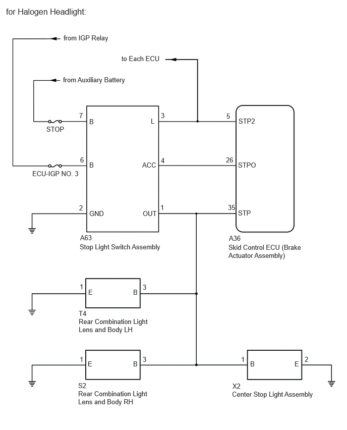
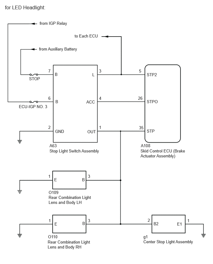
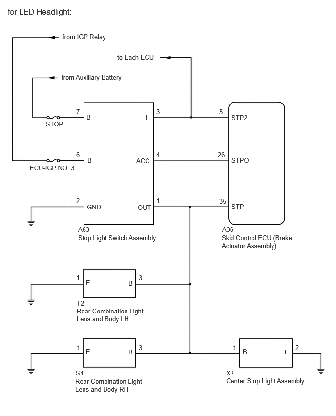
CAUTION / NOTICE / HINT
- NOTICE:
-
After replacing the skid control ECU (brake actuator assembly), perform "Calibration".
PROCEDURE
Check the vehicle specification.
- Result:
Result Proceed to for Halogen Headlight A for LED Headlight B
A
B
Pre-procedure1
Make sure that there is no looseness at the locking part and the connecting part of the connectors.
- OK:
The connector is securely connected.
Disconnect the A63 stop light switch assembly connector.
Check both the connector case and the terminals for deformation and corrosion.
- OK:
No deformation or corrosion.
Pre-procedure2
Turn the ignition switch to ON.
Procedure1
Check the illumination status of the brake lights.
Post-procedure1
Turn the ignition switch off.
- Result:
Result Proceed to The stop lights are illuminated A The stop lights are not illuminated B
A
B
Pre-procedure1
Reconnect the A63 stop light switch assembly connector.
Make sure that there is no looseness at the locking part and the connecting part of the connectors.
- OK:
The connector is securely connected.
Procedure1
Operate the GTS to check the Data List.
- Chassis > Brake > Data List
-
Tester Display Measurement Item Range Normal Condition Diagnostic Note Stop Light Relay STP2 terminal input OFF / ON OFF: STP2 terminal input OFF
ON: STP2 terminal input ON- HINT:
-
The stop light state is determined using the voltage at terminal STP2
- Chassis > Brake > Data List
-
Tester Display Stop Light Relay - 50003 435 67
With the brake pedal released, check the value of Data List item "Stop Light Relay".
Post-procedure1
Turn the ignition switch off.
- Result:
Result Proceed to The value of Stop Light Relay is OFF A The value of Stop Light Relay is ON B
A
B
Pre-procedure1
Make sure that there is no looseness at the locking part and the connecting part of the connectors.
- OK:
The connector is securely connected.
Disconnect the T4 rear combination light lens and body LH connector.
Check both the connector case and the terminals for deformation and corrosion.
- OK:
No deformation or corrosion.
Procedure1
Operate the GTS to check the Data List.
- Chassis > Brake > Data List
-
Tester Display Measurement Item Range Normal Condition Diagnostic Note Stop Light Relay STP2 terminal input OFF / ON OFF: STP2 terminal input OFF
ON: STP2 terminal input ON- HINT:
-
The stop light state is determined using the voltage at terminal STP2
- Chassis > Brake > Data List
-
Tester Display Stop Light Relay - 50003 435 67
With the brake pedal released, check the value of Data List item "Stop Light Relay".
Post-procedure1
Turn the ignition switch off.
- Result:
Result Proceed to The value of Stop Light Relay is OFF A The value of Stop Light Relay is ON B
A
Refer to "Left or right stop light does not illuminate" of problem symptoms table.
Click hereVehicle Exterior>LIGHTING (EXT)>LIGHTING SYSTEM>PROBLEM SYMPTOMS TABLE
B
Pre-procedure1
Make sure that there is no looseness at the locking part and the connecting part of the connectors.
- OK:
The connector is securely connected.
Disconnect the S2 rear combination light lens and body RH connector.
Check both the connector case and the terminals for deformation and corrosion.
- OK:
No deformation or corrosion.
Procedure1
Operate the GTS to check the Data List.
- Chassis > Brake > Data List
-
Tester Display Measurement Item Range Normal Condition Diagnostic Note Stop Light Relay STP2 terminal input OFF / ON OFF: STP2 terminal input OFF
ON: STP2 terminal input ON- HINT:
-
The stop light state is determined using the voltage at terminal STP2
- Chassis > Brake > Data List
-
Tester Display Stop Light Relay - 50003 435 67
With the brake pedal released, check the value of Data List item "Stop Light Relay".
Post-procedure1
Turn the ignition switch off.
- Result:
Result Proceed to The value of Stop Light Relay is OFF A The value of Stop Light Relay is ON B
A
Refer to "Left or right stop light does not illuminate" of problem symptoms table.
Click hereVehicle Exterior>LIGHTING (EXT)>LIGHTING SYSTEM>PROBLEM SYMPTOMS TABLE
B
Pre-procedure1
Make sure that there is no looseness at the locking part and the connecting part of the connectors.
- OK:
The connector is securely connected.
Disconnect the X2 center stop light assembly connector.
Check both the connector case and the terminals for deformation and corrosion.
- OK:
No deformation or corrosion.
Procedure1
Operate the GTS to check the Data List.
- Chassis > Brake > Data List
-
Tester Display Measurement Item Range Normal Condition Diagnostic Note Stop Light Relay STP2 terminal input OFF / ON OFF: STP2 terminal input OFF
ON: STP2 terminal input ON- HINT:
-
The stop light state is determined using the voltage at terminal STP2
- Chassis > Brake > Data List
-
Tester Display Stop Light Relay - 50003 435 67
With the brake pedal released, check the value of Data List item "Stop Light Relay".
Post-procedure1
Turn the ignition switch off.
- Result:
Result Proceed to The value of Stop Light Relay is OFF A The value of Stop Light Relay is ON B
A
B
Pre-procedure1
Make sure that there is no looseness at the locking part and the connecting part of the connectors.
- OK:
The connector is securely connected.
Disconnect the A36 skid control ECU (brake actuator assembly) connector.
Check both the connector case and the terminals for deformation and corrosion.
- OK:
No deformation or corrosion.
Pre-procedure2
Turn the ignition switch to ON.
Procedure1
Measure the voltage according to the value(s) in the table below.
- Standard Voltage:
Tester Connection Condition Specified Condition A36-5 (STP2) - Body ground Ignition switch ON 0 V
Post-procedure1
Turn the ignition switch off.
- Result:
Proceed to OK NG
OK
NG
Pre-procedure1
Make sure that there is no looseness at the locking part and the connecting part of the connectors.
- OK:
The connector is securely connected.
Disconnect the A36 skid control ECU (brake actuator assembly) connector.
Check both the connector case and the terminals for deformation and corrosion.
- OK:
No deformation or corrosion.
Pre-procedure2
Turn the ignition switch to ON.
Procedure1
Measure the resistance according to the value(s) in the table below.
- Standard Resistance:
Tester Connection Condition Specified Condition A63-4 (ACC) or A36-26 (STPO) - Body ground and other terminals Always 10 kΩ or higher
Post-procedure1
Turn the ignition switch off.
- Result:
Proceed to OK NG
OK
NG
Check the vehicle specification.
- Result:
Result Proceed to for 3 Door A for 5 Door B
A
B
Pre-procedure1
Make sure that there is no looseness at the locking part and the connecting part of the connectors.
- OK:
The connector is securely connected.
Disconnect the A63 stop light switch assembly connector.
Check both the connector case and the terminals for deformation and corrosion.
- OK:
No deformation or corrosion.
Pre-procedure2
Turn the ignition switch to ON.
Procedure1
Check the illumination status of the brake lights.
Post-procedure1
Turn the ignition switch off.
- Result:
Result Proceed to The stop lights are illuminated A The stop lights are not illuminated B
A
B
Pre-procedure1
Reconnect the A63 stop light switch assembly connector.
Make sure that there is no looseness at the locking part and the connecting part of the connectors.
- OK:
The connector is securely connected.
Procedure1
Operate the GTS to check the Data List.
- Chassis > Brake > Data List
-
Tester Display Measurement Item Range Normal Condition Diagnostic Note Stop Light Relay STP2 terminal input OFF / ON OFF: STP2 terminal input OFF
ON: STP2 terminal input ON- HINT:
-
The stop light state is determined using the voltage at terminal STP2
- Chassis > Brake > Data List
-
Tester Display Stop Light Relay - 50003 435 67
With the brake pedal released, check the value of Data List item "Stop Light Relay".
Post-procedure1
Turn the ignition switch off.
- Result:
Result Proceed to The value of Stop Light Relay is OFF A The value of Stop Light Relay is ON B
A
B
Pre-procedure1
Make sure that there is no looseness at the locking part and the connecting part of the connectors.
- OK:
The connector is securely connected.
Disconnect the O109 rear combination light lens and body LH connector.
Check both the connector case and the terminals for deformation and corrosion.
- OK:
No deformation or corrosion.
Procedure1
Operate the GTS to check the Data List.
- Chassis > Brake > Data List
-
Tester Display Measurement Item Range Normal Condition Diagnostic Note Stop Light Relay STP2 terminal input OFF / ON OFF: STP2 terminal input OFF
ON: STP2 terminal input ON- HINT:
-
The stop light state is determined using the voltage at terminal STP2
- Chassis > Brake > Data List
-
Tester Display Stop Light Relay - 50003 435 67
With the brake pedal released, check the value of Data List item "Stop Light Relay".
Post-procedure1
Turn the ignition switch off.
- Result:
Result Proceed to The value of Stop Light Relay is OFF A The value of Stop Light Relay is ON B
A
Refer to "Left or right stop light does not illuminate" of problem symptoms table.
Click hereVehicle Exterior>LIGHTING (EXT)>LIGHTING SYSTEM>PROBLEM SYMPTOMS TABLE
B
Pre-procedure1
Make sure that there is no looseness at the locking part and the connecting part of the connectors.
- OK:
The connector is securely connected.
Disconnect the O110 rear combination light lens and body RH connector.
Check both the connector case and the terminals for deformation and corrosion.
- OK:
No deformation or corrosion.
Procedure1
Operate the GTS to check the Data List.
- Chassis > Brake > Data List
-
Tester Display Measurement Item Range Normal Condition Diagnostic Note Stop Light Relay STP2 terminal input OFF / ON OFF: STP2 terminal input OFF
ON: STP2 terminal input ON- HINT:
-
The stop light state is determined using the voltage at terminal STP2
- Chassis > Brake > Data List
-
Tester Display Stop Light Relay - 50003 435 67
With the brake pedal released, check the value of Data List item "Stop Light Relay".
Post-procedure1
Turn the ignition switch off.
- Result:
Result Proceed to The value of Stop Light Relay is OFF A The value of Stop Light Relay is ON B
A
Refer to "Left or right stop light does not illuminate" of problem symptoms table.
Click hereVehicle Exterior>LIGHTING (EXT)>LIGHTING SYSTEM>PROBLEM SYMPTOMS TABLE
B
Pre-procedure1
Make sure that there is no looseness at the locking part and the connecting part of the connectors.
- OK:
The connector is securely connected.
Disconnect the g1 center stop light assembly connector.
Check both the connector case and the terminals for deformation and corrosion.
- OK:
No deformation or corrosion.
Procedure1
Operate the GTS to check the Data List.
- Chassis > Brake > Data List
-
Tester Display Measurement Item Range Normal Condition Diagnostic Note Stop Light Relay STP2 terminal input OFF / ON OFF: STP2 terminal input OFF
ON: STP2 terminal input ON- HINT:
-
The stop light state is determined using the voltage at terminal STP2
- Chassis > Brake > Data List
-
Tester Display Stop Light Relay - 50003 435 67
With the brake pedal released, check the value of Data List item "Stop Light Relay".
Post-procedure1
Turn the ignition switch off.
- Result:
Result Proceed to The value of Stop Light Relay is OFF A The value of Stop Light Relay is ON B
A
B
Pre-procedure1
Make sure that there is no looseness at the locking part and the connecting part of the connectors.
- OK:
The connector is securely connected.
Disconnect the A108 skid control ECU (brake actuator assembly) connector.
Check both the connector case and the terminals for deformation and corrosion.
- OK:
No deformation or corrosion.
Pre-procedure2
Turn the ignition switch to ON.
Procedure1
Measure the voltage according to the value(s) in the table below.
- Standard Voltage:
Tester Connection Condition Specified Condition A108-5 (STP2) - Body ground Ignition switch ON 0 V
Post-procedure1
Turn the ignition switch off.
- Result:
Proceed to OK NG
OK
for RHD: Click hereBrake>BRAKE CONTROL / DYNAMIC CONTROL SYSTEMS>BRAKE ACTUATOR (for Gasoline Model TMC Made RHD)>REMOVAL
for LHD: Click hereBrake>BRAKE CONTROL / DYNAMIC CONTROL SYSTEMS>BRAKE ACTUATOR (for Gasoline Model TMC Made LHD)>REMOVAL
NG
Pre-procedure1
Make sure that there is no looseness at the locking part and the connecting part of the connectors.
- OK:
The connector is securely connected.
Disconnect the A108 skid control ECU (brake actuator assembly) connector.
Check both the connector case and the terminals for deformation and corrosion.
- OK:
No deformation or corrosion.
Pre-procedure2
Turn the ignition switch to ON.
Procedure1
Measure the voltage according to the value(s) in the table below.
- Standard Resistance:
Tester Connection Condition Specified Condition A63-4 (ACC) or A108-26 (STPO) - Body ground and other terminals Always 10 kΩ or higher
Post-procedure1
Turn the ignition switch off.
- Result:
Proceed to OK NG
OK
for RHD: Click hereBrake>BRAKE CONTROL / DYNAMIC CONTROL SYSTEMS>BRAKE ACTUATOR (for Gasoline Model TMC Made RHD)>REMOVAL
for LHD: Click hereBrake>BRAKE CONTROL / DYNAMIC CONTROL SYSTEMS>BRAKE ACTUATOR (for Gasoline Model TMC Made LHD)>REMOVAL
NG
Pre-procedure1
Make sure that there is no looseness at the locking part and the connecting part of the connectors.
- OK:
The connector is securely connected.
Disconnect the A63 stop light switch assembly connector.
Check both the connector case and the terminals for deformation and corrosion.
- OK:
No deformation or corrosion.
Pre-procedure2
Turn the ignition switch to ON.
Procedure1
Check the illumination status of the brake lights.
Post-procedure1
Turn the ignition switch off.
- Result:
Result Proceed to The stop lights are illuminated A The stop lights are not illuminated B
A
B
Pre-procedure1
Reconnect the A63 stop light switch assembly connector.
Make sure that there is no looseness at the locking part and the connecting part of the connectors.
- OK:
The connector is securely connected.
Procedure1
Operate the GTS to check the Data List.
- Chassis > Brake > Data List
-
Tester Display Measurement Item Range Normal Condition Diagnostic Note Stop Light Relay STP2 terminal input OFF / ON OFF: STP2 terminal input OFF
ON: STP2 terminal input ON- HINT:
-
The stop light state is determined using the voltage at terminal STP2
- Chassis > Brake > Data List
-
Tester Display Stop Light Relay - 50003 435 67
With the brake pedal released, check the value of Data List item "Stop Light Relay".
Post-procedure1
Turn the ignition switch off.
- Result:
Result Proceed to The value of Stop Light Relay is OFF A The value of Stop Light Relay is ON B
A
B
Pre-procedure1
Make sure that there is no looseness at the locking part and the connecting part of the connectors.
- OK:
The connector is securely connected.
Disconnect the T2 rear combination light lens and body LH connector.
Check both the connector case and the terminals for deformation and corrosion.
- OK:
No deformation or corrosion.
Procedure1
Operate the GTS to check the Data List.
- Chassis > Brake > Data List
-
Tester Display Measurement Item Range Normal Condition Diagnostic Note Stop Light Relay STP2 terminal input OFF / ON OFF: STP2 terminal input OFF
ON: STP2 terminal input ON- HINT:
-
The stop light state is determined using the voltage at terminal STP2
- Chassis > Brake > Data List
-
Tester Display Stop Light Relay - 50003 435 67
With the brake pedal released, check the value of Data List item "Stop Light Relay".
Post-procedure1
Turn the ignition switch off.
- Result:
Result Proceed to The value of Stop Light Relay is OFF A The value of Stop Light Relay is ON B
A
Refer to "Left or right stop light does not illuminate" of problem symptoms table.
Click hereVehicle Exterior>LIGHTING (EXT)>LIGHTING SYSTEM>PROBLEM SYMPTOMS TABLE
B
Pre-procedure1
Make sure that there is no looseness at the locking part and the connecting part of the connectors.
- OK:
The connector is securely connected.
Disconnect the S4 rear combination light lens and body RH connector.
Check both the connector case and the terminals for deformation and corrosion.
- OK:
No deformation or corrosion.
Procedure1
Operate the GTS to check the Data List.
- Chassis > Brake > Data List
-
Tester Display Measurement Item Range Normal Condition Diagnostic Note Stop Light Relay STP2 terminal input OFF / ON OFF: STP2 terminal input OFF
ON: STP2 terminal input ON- HINT:
-
The stop light state is determined using the voltage at terminal STP2
- Chassis > Brake > Data List
-
Tester Display Stop Light Relay - 50003 435 67
With the brake pedal released, check the value of Data List item "Stop Light Relay".
Post-procedure1
Turn the ignition switch off.
- Result:
Result Proceed to The value of Stop Light Relay is OFF A The value of Stop Light Relay is ON B
A
Refer to "Left or right stop light does not illuminate" of problem symptoms table.
Click hereVehicle Exterior>LIGHTING (EXT)>LIGHTING SYSTEM>PROBLEM SYMPTOMS TABLE
B
Pre-procedure1
Make sure that there is no looseness at the locking part and the connecting part of the connectors.
- OK:
The connector is securely connected.
Disconnect the X2 center stop light assembly connector.
Check both the connector case and the terminals for deformation and corrosion.
- OK:
No deformation or corrosion.
Procedure1
Operate the GTS to check the Data List.
- Chassis > Brake > Data List
-
Tester Display Measurement Item Range Normal Condition Diagnostic Note Stop Light Relay STP2 terminal input OFF / ON OFF: STP2 terminal input OFF
ON: STP2 terminal input ON- HINT:
-
The stop light state is determined using the voltage at terminal STP2
- Chassis > Brake > Data List
-
Tester Display Stop Light Relay - 50003 435 67
With the brake pedal released, check the value of Data List item "Stop Light Relay".
Post-procedure1
Turn the ignition switch off.
- Result:
Result Proceed to The value of Stop Light Relay is OFF A The value of Stop Light Relay is ON B
A
B
Pre-procedure1
Make sure that there is no looseness at the locking part and the connecting part of the connectors.
- OK:
The connector is securely connected.
Disconnect the A36 skid control ECU (brake actuator assembly) connector.
Check both the connector case and the terminals for deformation and corrosion.
- OK:
No deformation or corrosion.
Pre-procedure2
Turn the ignition switch to ON.
Procedure1
Measure the voltage according to the value(s) in the table below.
- Standard Voltage:
Tester Connection Condition Specified Condition A36-5 (STP2) - Body ground Ignition switch ON 0 V
Post-procedure1
Turn the ignition switch off.
- Result:
Proceed to OK NG
OK
NG
Pre-procedure1
Make sure that there is no looseness at the locking part and the connecting part of the connectors.
- OK:
The connector is securely connected.
Disconnect the A36 skid control ECU (brake actuator assembly) connector.
Check both the connector case and the terminals for deformation and corrosion.
- OK:
No deformation or corrosion.
Pre-procedure2
Turn the ignition switch to ON.
Procedure1
Measure the voltage according to the value(s) in the table below.
- Standard Resistance:
Tester Connection Condition Specified Condition A63-4 (ACC) or A36-26 (STPO) - Body ground and other terminals Always 10 kΩ or higher
Post-procedure1
Turn the ignition switch off.
- Result:
Proceed to OK NG
OK
NG