CLUTCH CLUTCH MASTER CYLINDER(for RHD) INSTALLATION
PROCEDURE

 31410
1.INSTALL CLUTCH MASTER CYLINDER ASSEMBLY
Install a new clutch master cylinder gasket to the clutch master cylinder assembly.
Install the clutch master cylinder assembly to the vehicle body with the 2 nuts.
- Torque:
- 12.7 N*m (130 kgf*cm, 9 ft.*lbf)
31453A
2.INSTALL CLUTCH MASTER CYLINDER PUSH ROD CLEVIS WITH HOLE PIN
87211
3.INSTALL NO. 1 AIR DUCT
55606
4.INSTALL NO. 1 INSTRUMENT PANEL UNDER COVER SUB-ASSEMBLY
31481
5.CONNECT CLUTCH MASTER CYLINDER TO FLEXIBLE HOSE TUBE
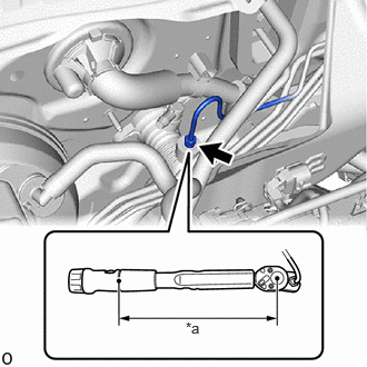
| *a | Torque Wrench Fulcrum Length |
Using a 10 mm union nut wrench, connect the clutch master cylinder to flexible hose tube to the clutch master cylinder assembly.
- Torque:
- Specified Tightening Torque : 15.2 N*m (155 kgf*cm, 11 ft.*lbf)
- NOTICE:
- ·
Do not kink or damage the clutch master cylinder to flexible hose tube.
·Do not allow any foreign matter such as dirt or dust to enter the clutch master cylinder to flexible hose tube from the connecting part.
- HINT:
- ·
Calculate the torque wrench reading when changing the fulcrum length of the torque wrench.
Click hereGeneral>INTRODUCTION>REPAIR INSTRUCTION>PRECAUTION
·When using a union nut wrench (fulcrum length of 22 mm (0.866 in.)) + torque wrench (fulcrum length of 162 mm (6.38 in.)):
13.4 N*m (137 kgf*cm, 10 ft.*lbf)
31434E
6.CONNECT NO. 1 CLUTCH RESERVOIR HOSE
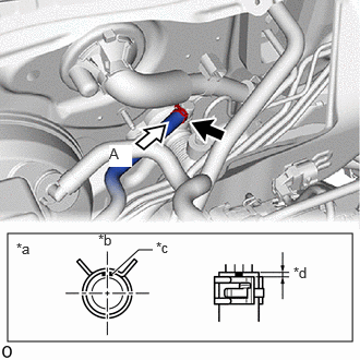
| *a | View A |
| *b | Top of Vehicle |
| *c | Paint Mark (Top of Vehicle) |
| *d | 0 to 2 mm (0 to 0.0787 in.) |
Connect the No. 1 clutch reservoir hose to the clutch master cylinder assembly and slide the hose clip to secure it.
- NOTICE:
- ·
Make sure that the paint mark of the No. 1 clutch reservoir hose is within the location shown in the illustration.
·Make sure that the claws of the hose clip are within the location shown in the illustration.
55225
7.INSTALL DASH PANEL HEAT INSULATOR (for G16E-GTS)
8.BLEED CLUTCH LINE
for C551:
Click hereDrivetrain>CLUTCH>CLUTCH SYSTEM (for C551)>BLEEDING
for EA67F:
Click hereDrivetrain>CLUTCH>CLUTCH SYSTEM (for EA67F)>BLEEDING
for EC6E:
Click hereDrivetrain>CLUTCH>CLUTCH SYSTEM (for EC6E)>BLEEDING
9.INSPECT FOR BRAKE FLUID LEAK
10.INSPECT BRAKE FLUID LEVEL IN RESERVOIR
for G16E-GTS:
Click hereBrake>BRAKE SYSTEM (OTHER)>BRAKE FLUID (for Gasoline Model)>ON-VEHICLE INSPECTION
except G16E-GTS:
Click hereBrake>BRAKE SYSTEM (OTHER)>BRAKE FLUID (for Gasoline Model)>ON-VEHICLE INSPECTION
55701J
11.INSTALL OUTER COWL TOP PANEL SUB-ASSEMBLY
55735A
12.INSTALL WATER GUARD PLATE LH
55815E
13.INSTALL FRONT NO. 1 VENTILATOR SEAL
14.INSTALL WINDSHIELD WIPER MOTOR AND LINK
15.INSPECT CLUTCH PEDAL