POWER DISTRIBUTION FUSIBLE LINK(for 120A DC/DC) INSTALLATION
PROCEDURE

 82210P
1.INSTALL ENGINE ROOM FUSIBLE LINK
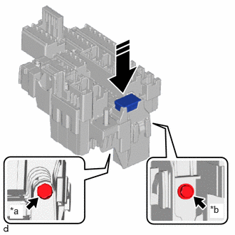
| *a | Bolt A |
| *b | Bolt B |

|
Install in this Direction |
Install the engine room fusible link with the bolt A and bolt B as shown in the illustration.
- Torque:
- Bolt A : 5.4 N*m (55 kgf*cm, 48 in.*lbf)
- Bolt B : 4.5 N*m (46 kgf*cm, 40 in.*lbf)
82610A
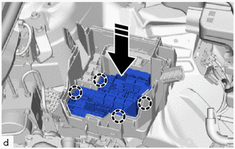
2.INSTALL FUSE BLOCK ASSEMBLY
|
|
Install in this Direction |
Engage the claws to install the fuse block assembly as shown in the illustration.
|
|
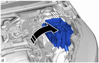
Move in this Direction |
Move the engine room relay block as shown in the illustration.
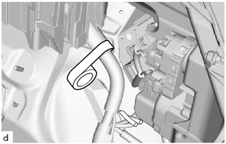
Install the vinyl tape is wrapped around the engine room relay block assembly 4 times as shown in the illustration.
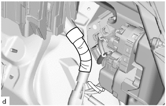
The vinyl tape is wrapped to the wire harness junction as shown in the illustration.
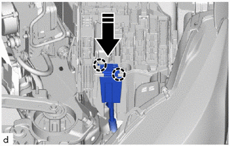
|
|
Connect in this Direction |
Engage the claws to connect the wire harness as shown in the illustration.
82663
3.INSTALL RELAY BLOCK LOWER COVER
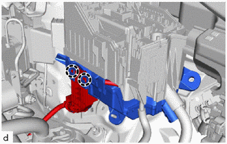
Insert the relay block lower cover under the engine room relay block.
Engage the claws to connect the wire harness.
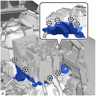
Engage the claws to install the relay block lower cover.
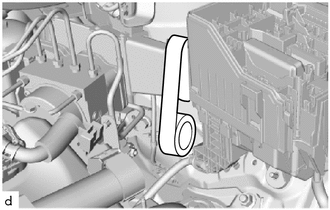
Install the wire harness repair tape is wrapped around the engine room relay block assembly 3 times as shown in the illustration.
The wire harness repair tape is wrapped as shown in the illustration.
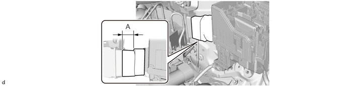
- Reference Measurement:
Area Measurement Area Measurement A 20 mm (0.787 in.) - -
The wire harness repair tape is wrapped as shown in the illustration.
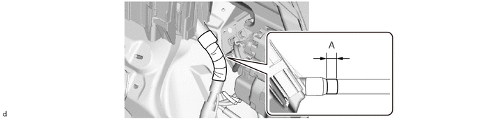
- Reference Measurement:
Area Measurement Area Measurement A 10 mm (0.394 in.) - -
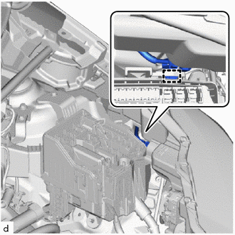
Engage the clamp to connect the wire harness.
Remove the protective tape.
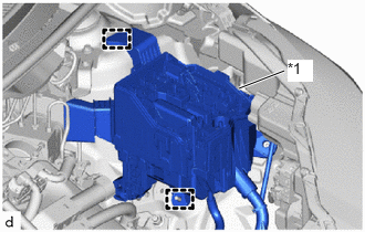
| *1 | Engine Room Relay Block Assembly |
Engage the guides to install the engine room relay block assembly.
Install the 2 bolts and nut.
- Torque:
- 10 N*m (102 kgf*cm, 7 ft.*lbf)
for RHD:
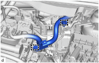
Engage the clamps to connect the wire harness.
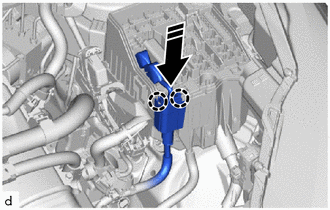
|
|
Connect in this Direction |
Engage the claws to connect the wire harness as shown in the illustration.
Connect the 2 connectors.
Install the nut.
- Torque:
- 10 N*m (102 kgf*cm, 7 ft.*lbf)
89730A
4.INSTALL SECURITY WARNING RELAY
Install the security warning relay.
85912K
5.INSTALL VVT RELAY
Install the VVT relay.
85948
6.INSTALL WINDSHIELD WIPER RELAY
Install the windshield wiper relay.
28371
7.INSTALL NO. 1 IGNITION RELAY
Install the No. 1 ignition relay.
82662A
8.INSTALL NO. 1 RELAY BLOCK COVER
89661
9.INSTALL ECM
10.INSTALL AIR CLEANER ASSEMBLY WITH AIR CLEANER HOSE