P0562 System Voltage Low
Diagnostic trouble codes · Vehicles built from Aug 2005
Also covers:
- P0563 System Voltage High
DESCRIPTION
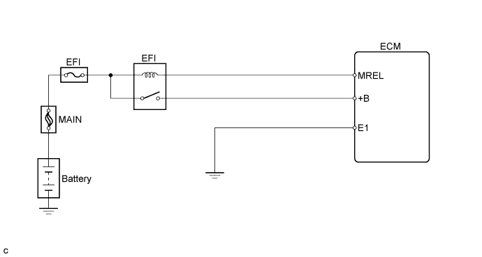
When the ignition switch is turned on (IG), the battery voltage is applied to terminal +B of the ECM.| DTC No. |
DTC Detection Condition |
Trouble Area |
| P0562 |
Battery voltage is between 2.5 V and 10 V when 180 seconds or more have elapsed since engine start (3 trip detection logic) |
|
| P0563 |
Battery voltage is 17 V or more when vehicle speed is 25 km/h (16 mph) or more, after 180 seconds or more have elapsed since engine start (3 trip detection logic). |
|
- HINT:
- DTC P0562 is detected when the engine idles for 180 seconds or more.
- DTC P0563 is detected when the vehicle speed is 25 km/h (16 mph) or more and 180 seconds or more have elapsed since engine start.
- DTC P0562 is detected when the engine idles for 180 seconds or more.
WIRING DIAGRAM

INSPECTION PROCEDURE
- NOTICE:
- Perform electronic throttle learning after replacing the ECM (Click here).
- HINT:
- Read freeze frame data using the intelligent tester. The ECM records vehicle and driving condition information as freeze frame data the moment a DTC is stored. When troubleshooting, freeze frame data can help determine if the vehicle was moving or stationary, if the engine was warmed up or not, if the air-fuel ratio was lean or rich, and other data from the time the malfunction occurred.
| 1. CHECK OUTPUT DTC |

Connect the intelligent tester to the DLC3.
Turn the ignition switch on (IG) and turn the tester ON.
Select the following menu items: Powertrain / Engine and ECT / DTC.
Read DTCs.
- Result:
Display (DTC Output)
Proceed To
P0562
A
P0563
B
|
|
||||

| A | |
 |
| 2. INSPECT FUSE (EFI FUSE) |
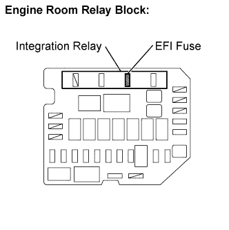 |
Remove the EFI fuse from the engine room relay block.
Check the EFI fuse resistance.
- Standard resistance:
- Below 1 Ω
Reinstall the EFI fuse.
|
|
||||

| OK | |
|
| 3. CHECK HARNESS AND CONNECTOR (INTEGRATION RELAY - ECM) |
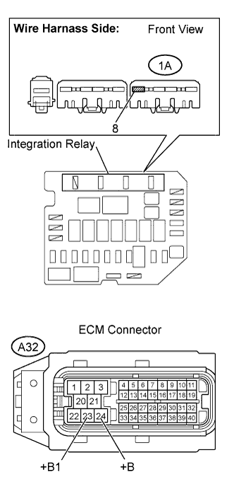 |
Remove the integration relay from the engine room relay block.
Disconnect the ECM connector.
Check the resistance.
- Standard resistance (Check for open):
Tester Connection
Specified Condition
+B (A32-24) - Integration relay (1A-8)
Below 1 Ω
+B1 (A32-23) - Integration relay (1A-8)
Below 1 Ω
- Standard resistance (Check for short):
Tester Connection
Specified Condition
+B (A32-24) - Body ground
10 kΩ or higher
+B1 (A32-23) - Body ground
10 kΩ or higher
Reinstall the integration relay.
Reconnect the ECM connector.
|
|
||||
| OK | |
|
| 4. INSPECT CHARGING SYSTEM AND BATTERY |
|
|
||||
| OK | ||
 |
||
| ||