INSTALLATION
Removal / installation · Vehicles built from Nov 2005
| 1. INSTALL STEERING COLUMN ASSEMBLY |

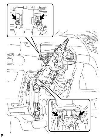  |
Install the steering column assembly onto the instrument panel reinforcement assembly with the bolt and 2 nuts.
- Torque:
- 25 N*m{ 255 kgf*cm , 18 ft.*lbf }
Connect all the connectors and clamp the wire harnesses onto the steering column assembly bracket.
| 2. INSTALL BRAKE PEDAL (for Automatic Transaxle) |
Apply lithium soap base glycol grease to the brake master cylinder push rod clevis pin and installation surfaces.
Install the brake pedal through the 2 brake pedal bushes with the nut and brake pedal shaft.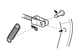
- Torque:
- 37 N*m{ 375 kgf*cm , 27 ft.*lbf }
Connect the brake master cylinder push rod clevis to the brake pedal with the brake master cylinder push rod clevis pin, install the clip onto the brake master cylinder push rod clevis pin, and then install the brake pedal return spring.
| 3. INSTALL BRAKE PEDAL SUPPORT SUB-ASSEMBLY (for Manual Transaxle) |
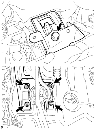 |
Install the pedal support with the bolt and 4 nuts.
- Torque:
- Bolt:
- 24 N*m{ 241 kgf*cm , 17 ft.*lbf }
- Nut:
- 9.0 N*m{ 92 kgf*cm , 80 in.*lbf }
| 4. INSTALL BRAKE MASTER CYLINDER PUSH ROD CLEVIS (for Manual Transaxle) |
Apply lithium soap base glycol grease to the push rod pin.
Install the push rod clevis with the push rod pin and clip.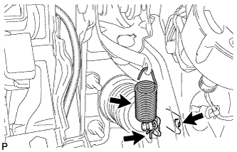
Install the brake pedal return spring.
| 5. INSTALL STEERING INTERMEDIATE SHAFT ASSEMBLY NO. 2 |
 |
Connect all the connectors and clamp the wire harnesses onto the steering column assembly bracket.
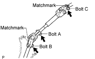
Align the matchmarks on steering intermediate shaft assembly No. 2 and the steering sliding yoke and provisionally install them with bolt C.
- Torque:
- 28 N*m{ 290 kgf*cm , 21 ft.*lbf }
Align the matchmarks on the steering sliding yoke and steering gear assembly and install them with bolt B.
- Torque:
- 28 N*m{ 290 kgf*cm , 21 ft.*lbf }
Tighten bolt A.
- Torque:
- 28 N*m{ 290 kgf*cm , 21 ft.*lbf }
| 6. INSTALL COLUMN HOLE COVER SILENCER SHEET |
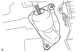 |
Install the column hole cover plate with the 2 clips.
Install the floor carpet.
| 7. INSTALL INSTRUMENT PANEL UNDER TRAY (w/o Knee Airbag) |
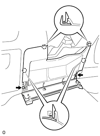 |
Engage the 4 claws and install the instrument panel under tray.
Install the 2 <A> screws.
Engage the 4 claws and install the instrument panel under tray.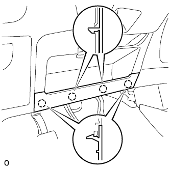
| 8. INSTALL DRIVER SIDE KNEE AIRBAG ASSEMBLY (w/ Knee Airbag) |
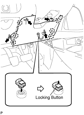 |
Engage the 6 claws.
Install the driver side knee airbag assembly with the 4 bolts.
- Torque:
- 10 N*m{ 102 kgf*cm , 7 ft.*lbf }
| 9. INSTALL INSTRUMENT PANEL UNDER COVER SUB-ASSEMBLY NO. 1 |
Engage the 4 claws and install the instrument panel under cover.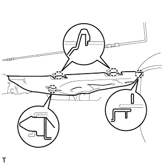
| 10. CONNECT POWER STEERING ECU |
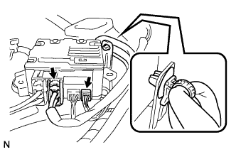 |
Connect the 2 steering column assembly connectors to the power steering ECU.
Install the power steering motor harness and torque sensor wire harness clamps onto the side of the power steering ECU.
Tilt the steering column assembly up and down to make sure that the power steering motor harness and torque sensor wire harness do not interfere with any components.
| 11. INSTALL MULTI-MODE MANUAL TRANSAXLE ECU (for Multi-Mode Manual Transaxle LHD) |
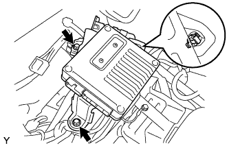 |
Engage the clip and install the transmission control ECU.
Install the 2 bolts.
- Torque:
- 8.0 N*m{ 82 kgf*cm , 71 in.*lbf }
Connect the 3 connectors.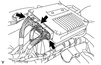
| 12. INSTALL INSTRUMENT PANEL SUB-ASSEMBLY UPPER |
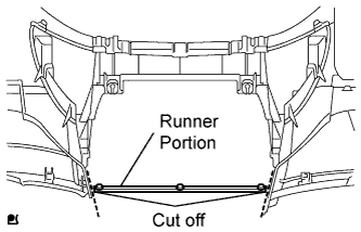 |
Using a nipper, cut off both ends of the runner portion shown in the illustration (When installing a new one).
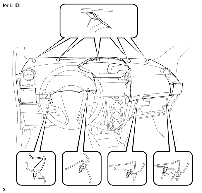
Engage the 5 claws at the upper side of the instrument panel.
Engage the claw and the 3 clips at the lower side of the instrument panel.
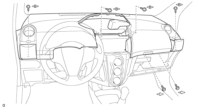
Install the instrument panel upper with the 2 <C> bolts and the 4 <B> screws.
- Torque:
- 20 N*m{ 204 kgf*cm , 15 ft.*lbf } for bolt
Connect the connectors.
Connect the passenger airbag connector and clamp.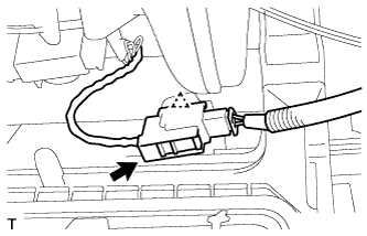
| 13. INSTALL SWITCH BASE HOLE COVER |
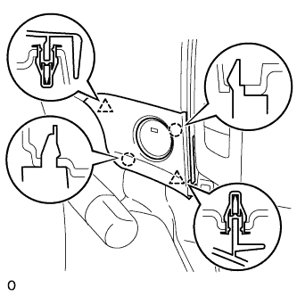 |
Disengage the 2 clips and 2 claws and install the switch hole base.
| 14. INSTALL GLOVE COMPARTMENT DOOR ASSEMBLY |
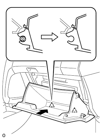 |
Engage the claw of the hinge portion in the horizontal direction to install the glove compartment door assembly.
- NOTICE:
- Engage the claw in the horizontal direction, otherwise, installation failure caused by excessive play around the hinge portion will result.
Slightly deform the upper portion of the glove compartment door assembly to engage the stopper.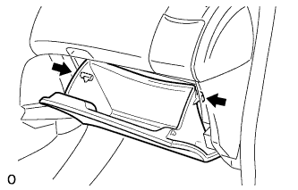
| 15. INSTALL FRONT PILLAR GARNISH RH |
w/ Curtain Shield Airbag: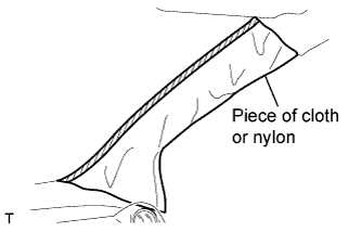
Remove the piece of cloth or nylon.
w/ Front No. 2 Speaker: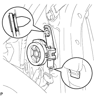
Insert the hook into the body hole.
Engage the clip and install the front speaker.
Connect the speaker connector.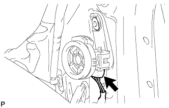
Install the 3 antenna cord clamps.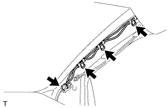
Connect the connector.
w/ Curtain Shield Airbag:
Install a new special clip and the clip onto a new front pillar garnish.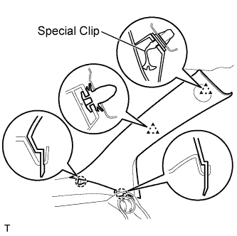
Engage the 2 clips and the 2 claws and install the front pillar garnish.
w/o Curtain Shield Airbag:
Engage the 2 clips and the 2 claws and install the front pillar garnish.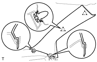
| 16. INSTALL FRONT PILLAR GARNISH LH |
w/ Curtain Shield Airbag: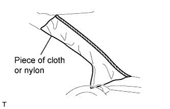
Remove the piece of cloth or nylon.
w/ Front No. 2 Speaker: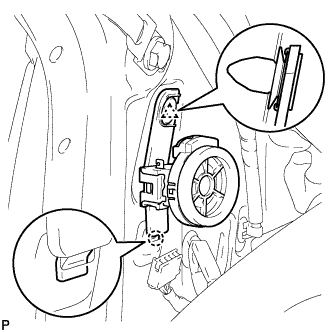
Insert the hook into the body hole.
Engage the clip and install the front speaker.
Connect the speaker connector.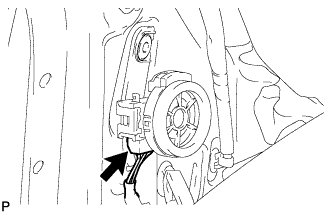
Install the 4 wire harness clamps.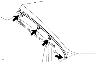
w/ Curtain Shield Airbag:
Install a new special clip and the clip onto a new front pillar garnish.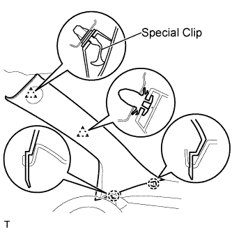
Engage the 2 clips and the 2 claws and install the front pillar garnish.
w/o Curtain Shield Airbag:
Engage the 2 clips and the 2 claws and install the front pillar garnish.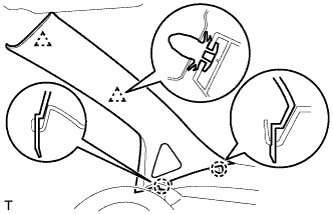
| 17. INSTALL FRONT DOOR OPENING TRIM WEATHERSTRIP RH |
Install the front door opening trim weatherstrip.
| 18. INSTALL FRONT DOOR OPENING TRIM WEATHERSTRIP LH |
- HINT:
- Use the same procedure for the RH side as for the LH side.
| 19. INSTALL INSTRUMENT CLUSTER FINISH PANEL SUB-ASSEMBLY CENTER |
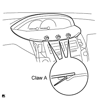 |
Fit the 3 A claws of the instrument cluster finish panel into the upper instrument cluster finish panel center.
Engage the 4 claws and 5 clips and install the instrument cluster finish panel.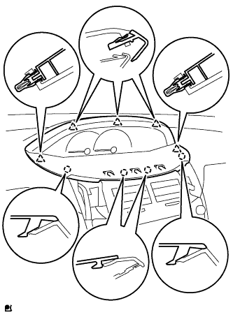
| 20. INSTALL COMBINATION METER ASSEMBLY |
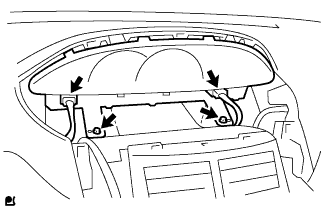 |
Install the combination meter assembly with the 2 screws.
Connect the 2 connectors.
| 21. INSTALL INSTRUMENT CLUSTER FINISH PANEL |
|
|
Fit the 3 A claws of the instrument cluster finish panel into the upper instrument cluster finish panel center.
Engage the 4 claws and 5 clips and install the instrument cluster finish panel.
| 22. INSTALL INSTRUMENT PANEL FINISH PANEL END RH |
 |
with CD player
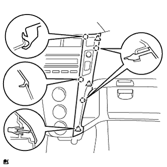
Connect the connector.
Engage the 4 claws and 3 clips and install the instrument panel finish panel end RH.
Except CD player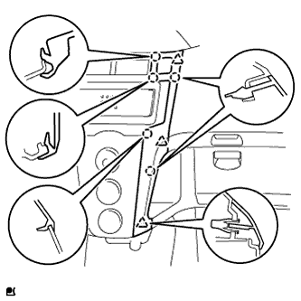
Connect the connector.
Engage the 5 claws and 3 clips and install the instrument panel finish panel end RH.
| 23. INSTALL INSTRUMENT PANEL FINISH PANEL END LH |
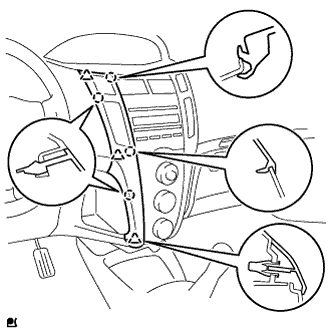 |
with CD player
Connect the connector.
Engage the 4 claws and 3 clips and install the instrument panel finish panel end LH.
Except CD player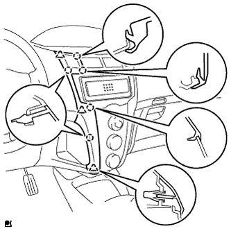
Connect the connector.
Engage the 5 claws and 3 clips and install the instrument panel finish panel end LH.
| 24. INSTALL COMBINATION SWITCH ASSEMBLY |
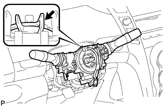 |
Install combination switch assembly with the clamp.
Connect all the connectors to the turn signal switch with spiral cable.
| 25. INSTALL STEERING COLUMN COVER |
Engage the claw to install the steering column upper cover.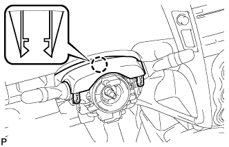
w/o Entry and Start System:
Engage the 2 claws to install the steering column lower cover.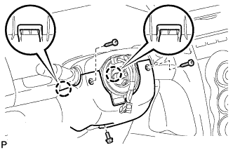
Install the 3 screws.
w/ Entry and Start System:
Engage the 3 claws to install the steering column lower cover and steering column cover support.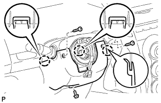
Install the 3 screws.
| 26. INSTALL STEERING WHEEL ASSEMBLY |
Align the matchmarks and install the steering wheel assembly onto the steering column assembly.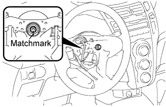
Install the nut.
- Torque:
- 50 N*m{ 510 kgf*cm , 37 ft.*lbf }
Connect all connectors to the spiral cable.
| 27. INSTALL STEERING PAD (w/o Steering Pad Switch) |
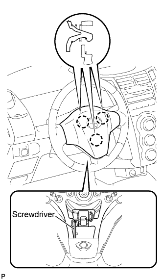 |
Insert a screwdriver 20cm into the hole in the back side of the steering wheel and raise the spring slightly until its release is felt and disengage the lower claw.
Push out the steering pad in the direction shown in the illustration and disengage the 2 claws.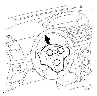
Using a thin-bladed screwdriver, release the locking button.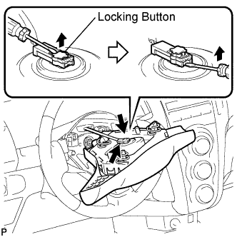
Using a thin-bladed screwdriver, detach the airbag connector.
Detach the horn terminal.
| 28. INSTALL STEERING PAD (w/ Steering Pad Switch) |
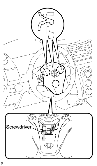 |
Insert a screwdriver 20cm into the hole in the back side of the steering wheel and raise the spring slightly until its release is felt and disengage the lower claw.
Push out the steering pad in the direction shown in the illustration and disengage the 2 claws.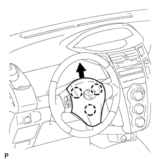
Using a thin-bladed screwdriver, release the locking button.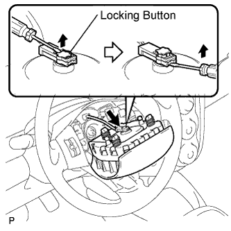
Using a thin-bladed screwdriver, detach the airbag connector.
Detach the horn terminal.
| 29. POSITION FRONT WHEEL FACING STRAIGHT AHEAD |
| 30. CONNECT CABLE TO NEGATIVE BATTERY TERMINAL |
- Torque:
- 5.4 N*m{ 55 kgf*cm , 48 in.*lbf }
| 31. CHECK SRS WARNING LIGHT TURNS OFF |
| 32. PERFORM CALIBRATION OF TORQUE SENSOR ZERO POINT |
| 33. LEARNING OF MULTI-MODE MANUAL TRANSAXLE SYSTEM (for Multi-Mode Manual Transaxle LHD) |
| 34. PERFORM SYNCHRONIZATION POSITION CALIBRATION (for Multi-Mode Manual Transaxle LHD) |