Front Passenger Side Power Window does not Operate with Front Passenger Side Power Window Switch
Circuit diagnosis · Vehicles built from Nov 2005
DESCRIPTION
- When the engine is running or the ignition switch is on (IG) and the window lock switch of the power window regulator master switch assembly is normal, the front passenger door power window regulator motor is driven by operating the front passenger door power window regulator switch.
WIRING DIAGRAM
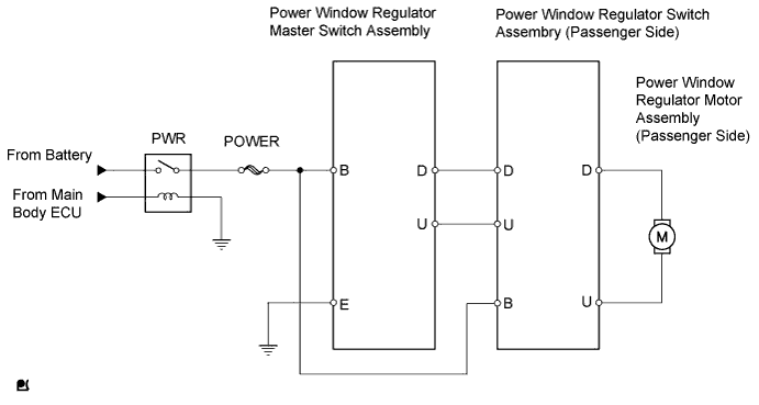

INSPECTION PROCEDURE
| 1. CHECK HARNESS AND CONNECTOR (INPUT POWER SUPPLY) |

Disconnect the F1 or G7 power window regulator switch (passenger side) connector.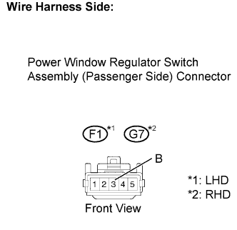
Turn the ignition switch to on (IG).
Measure the voltage of the wire harness side connector.
- Standard voltage:
LHD Tester Connection
Specified Condition
F1-3 - Body ground
10 to 14 V
RHD Tester Connection
Specified Condition
G7-3 - Body ground
10 to 14 V
Reconnect the power window regulator switch (passenger side) connector.
|
|
||||

| OK | |
 |
| 2. INSPECT POWER WINDOW REGULATOR SWITCH ASSEMBLY |
Remove the power window regulator switch assembly (Click here).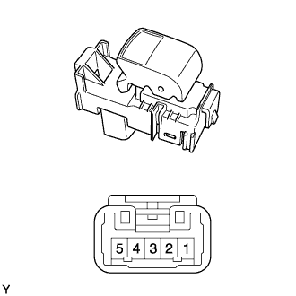
Measure the resistance of the switch when the switch is operated.
- Standard resistance:
Tester Connection
Switch Connection
Specified Condition
1 - 2
3 - 4
UP
Below 1 Ω
1 - 2
4 - 5
OFF
Below 1 Ω
1 - 3
4 - 5
DOWN
Below 1 Ω
Reinstall the power window regulator switch assembly.
|
|
||||
| OK | |
|
| 3. CHECK HARNESS AND CONNECTOR (SWITCH (PASSENGER SIDE) - MOTOR (PASSENGER SIDE)) |
Disconnect the F1 or G7 power window regulator switch (passenger side) connector.
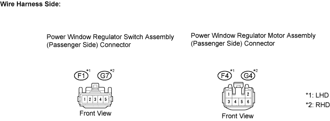
Disconnect the F4 or G4 power window regulator motor (passenger side) connector.
Measure the resistance of the wire harness side connectors.
- Standard resistance:
LHD Tester Connection
Specified Condition
F1-4 - F4-2
Below 1 Ω
F1-1 - F4-1
Below 1 Ω
F1-4 or F4-2 - Body ground
10 kΩ or higher
F1-1 or F4-1 - Body ground
10 kΩ or higher
RHD Tester Connection
Specified Condition
G7-4 - G4-2
Below 1 Ω
G7-1 - G4-1
Below 1 Ω
G7-4 or G4-2 - Body ground
10 kΩ or higher
G7-1 or G4-1 - Body ground
10 kΩ or higher
|
|
||||
| OK | |
|
| 4. INSPECT POWER WINDOW REGULATOR MOTOR ASSEMBLY (PASSENGER SIDE) |
LHD: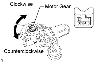
Remove the power window regulator motor assembly.
Apply the battery voltage to connector terminals 1 and 2.
- NOTICE:
- Do not apply the battery voltage to any terminals except terminals 1 and 2.
Check that the motor gear rotates smoothly as follows.
- OK:
Measurement Condition
Specified Condition
Battery positive (+) → 1
Battery negative (-) → 2
Motor gear rotates clockwise
Battery positive (+) → 2
Battery negative (-) → 1
Motor gear rotates counterclockwise
Reinstall the power window regulator motor assembly.
RHD: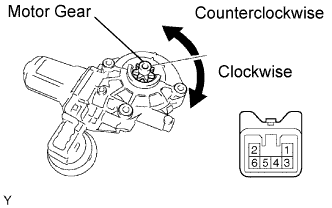
Remove the power window regulator motor assembly.
Apply the battery voltage to connector terminals 1 and 2.
- NOTICE:
- Do not apply the battery voltage to any terminals except terminals 1 and 2.
Check that the motor gear rotates smoothly as follows.
- OK:
Measurement Condition
Specified Condition
Battery positive (+) → 1
Battery negative (-) → 2
Motor gear rotates counterclockwise
Battery positive (+) → 2
Battery negative (-) → 1
Motor gear rotates clockwise
Reinstall the power window regulator motor assembly.
|
|
||||
| OK | |
|
| 5. CHECK HARNESS AND CONNECTOR (MASTER SWITCH - REGULATOR SWITCH) |
Disconnect the G1 or F7 power window regulator master switch connector.
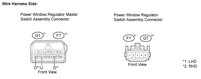
Disconnect the F1 or G7 power window regulator switch connector.
Measure the resistance of the wire harness side connectors.
- Standard resistance:
LHD Tester Connection
Specified Condition
G1-12 (U) - F1-5
Below 1 Ω
G1-16 (D) - F1-2
Below 1 Ω
G1-12 (U) or F1-5 - Body ground
10 kΩ or higher
G1-16 (D) or F1-2 - Body ground
10 kΩ or higher
RHD Tester Connection
Specified Condition
F7-12 (U) - G7-5
Below 1 Ω
F7-10 (D) - G7-2
Below 1 Ω
F7-12 (U) or G7-5 - Body ground
10 kΩ or higher
F7-10 (D) or G7-2 - Body ground
10 kΩ or higher
Reconnect the power window regulator switch connectors.
|
|
||||
| OK | |
|
| 6. INSPECT POWER WINDOW REGULATOR MASTER SWITCH ASSEMBLY (FOR FRONT PASSENGER SWITCH) |
LHD: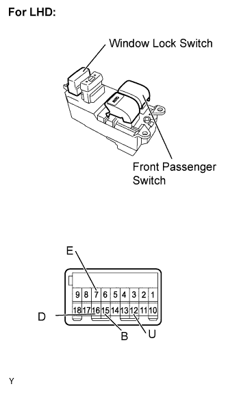
Remove the master switch (Click here).
Measure the resistance of the switch when the switch is operated.
- Standard resistance:
Passenger side switch: Window Lock Switch Condition
Power Window Switch Condition
Tester Connection
Specified Condition
OFF
UP
16 (D) - 7 (E)
12 (U) - 15 (B)
Below 1 Ω
OFF
OFF
12 (U) - 7 (E)
16 (D) - 7 (E)
Below 1 Ω
OFF
DOWN
12 (U) - 7 (E)
15 (B) - 16 (D)
Below 1 Ω
ON
UP
12 (U) - 15 (B)
Below 1 Ω
ON
OFF
12 (U) - 16 (D)
Below 1 Ω
ON
DOWN
15 (B) - 16 (D)
Below 1 Ω
Reinstall the master switch.
RHD: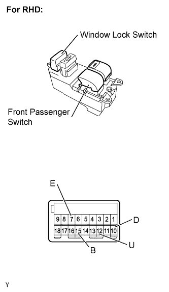
Remove the master switch (Click here).
Measure the resistance of the switch when the switch is operated.
- Standard resistance:
Passenger side switch: Window Lock Switch Condition
Power Window Switch Condition
Tester Connection
Specified Condition
OFF
UP
10 (D) - 7 (E)
12 (U) - 15 (B)
Below 1 Ω
OFF
OFF
12 (U) - 7 (E)
10 (D) - 7 (E)
Below 1 Ω
OFF
DOWN
12 (U) - 7 (E)
15 (B) - 10 (D)
Below 1 Ω
ON
UP
12 (U) - 15 (B)
Below 1 Ω
ON
OFF
12 (U) - 10 (D)
Below 1 Ω
ON
DOWN
15 (B) - 10 (D)
Below 1 Ω
Reinstall the master switch.
|
|
||||
| OK | ||
 |
||
| ||