Steering Lock Motor Drive Power Circuit
Circuit diagnosis · Vehicles built Aug 2005 – Oct 2005
Versions by build date: Aug 2005 – Oct 2005 from Nov 2005
DESCRIPTION
The main body ECU supplies the power to activate the motor of the steering lock actuator assembly.The diagnosis information of the steering lock ECU is transmitted to the tester via the certification ECU as the steering lock ECU is not connected to the CAN communication system.
WIRING DIAGRAM
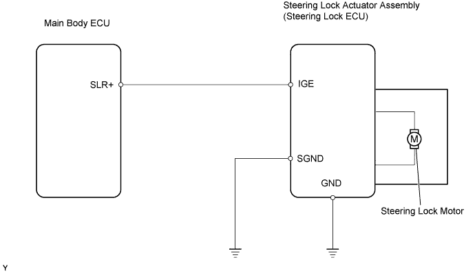

INSPECTION PROCEDURE
- HINT:
- Before starting the inspection by using the intelligent tester with the engine switch off, make sure that the driver door is open.
- When the engine switch is off, the main body ECU may not be working.
- Communication with the intelligent tester is impossible if the main body ECU is not working.
- Before starting the inspection by using the intelligent tester with the engine switch off, make sure that the driver door is open.
| 1. CHECK DTC (CERTIFICATION ECU) |

Connect the intelligent tester to the DLC3.
Turn the engine switch on (IG) and turn the tester on.
Read the DTCs of the certification ECU by following the prompts displayed on the intelligent tester.
- OK:
- DTC B2785 that indicates malfunctions in LIN bus line, is not output.
- HINT:
- If DTC B2785 is output, inspect LIN communication system (Click here ).
|
|
||||

| OK | |
 |
| 2. READ VALUE OF DATA LIST (LOCK/UNLOCK RECEIVE) |
Select the item [LOCK / UNLOCK RECEIVE] in the DATA LIST within 10 seconds of starting the engine.
- OK:
- [YES] is displayed on the tester screen.
|
|
||||

| OK | |
|
| 3. INSPECT STEERING LOCK ACTUATOR ASSEMBLY |
Measure the voltage.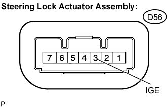
- Standard voltage:
Tester Connection
Condition
Specified Condition
IGE (D56-3) - Body ground
Turn engine switch off
↓
Turn engine switch on (IG)
Motor inactive:
10 to 14 V
↓
Motor active:
Below 1 V
↓
Motor inactive:
10 to 14 V
|
|
||||
| NG | |
|
| 4. CHECK HARNESS AND CONNECTOR (STEERING LOCK ACTUATOR ASSEMBLY - MAIN BODY ECU) |
Disconnect the connectors from the steering lock actuator assembly and the main body ECU.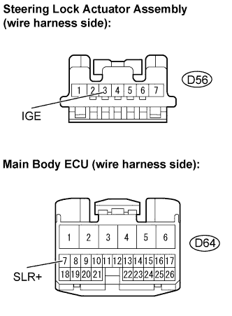
Measure the resistance.
- Standard resistance:
Tester Connection
Condition
Specified Condition
IGE (D56-3) - SLR+ (D64-7)
Always
Below 1 Ω
IGE (D56-3) - Body ground
Always
10 kΩ or higher
Reconnect the connectors.
|
|
||||
| OK | ||
 |
||
| ||
| 5. CHECK HARNESS AND CONNECTOR (STEERING LOCK ACTUATOR ASSEMBLY - BODY GROUND) |
Disconnect the connector from the steering lock actuator assembly.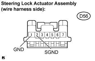
Measure the resistance.
- Standard resistance:
Tester Connection
Condition
Specified Condition
GND (D56-1) - Body ground
Always
Below 1 Ω
SGND (D56-2) - Body ground
Always
Below 1 Ω
|
|
||||
| OK | ||
|
||
| ||
| 6. READ VALUE OF DATA LIST (S CODE CHECK) |
Connect the intelligent tester to the DLC3.
Select the item [S CODE CHECK] in the DATA LIST.
- OK:
- [YES] is displayed on the tester screen.
|
|
||||
| NG | |
|
| 7. REPLACE ID CODE BOX |
Reconfirm the item [S CODE CHECK] in the DATA LIST of the certification ECU.
- OK:
- [YES] is displayed on the tester screen.
|
|
||||
| NG | ||
|
||
| ||
| 8. READ VALUE OF DATA LIST (L CODE CHECK) |
Select the item [L CODE CHECK] in the DATA LIST.
- OK:
- [YES] is displayed on the tester screen.
|
|
||||
| NG | |
|
| 9. REPLACE ID CODE BOX |
Reconfirm the item [L CODE CHECK] in the DATA LIST of the certification ECU.
- OK:
- [YES] is displayed on the tester screen.
|
|
||||
| NG | |
|
| 10. REPLACE STEERING LOCK ACTUATOR ASSEMBLY |
Replace the steering lock actuator assembly (Click here ).
Perform the confirmation test.
|
|
||||
| NG | ||
|
||
| ||