P0365 Camshaft Position Sensor "B" Circuit (Bank 1)
Diagnostic trouble codes · Vehicles built from Nov 2006
Also covers:
- P0367 Camshaft Position Sensor "B" Circuit Low Input (Bank 1)
- P0368 Camshaft Position Sensor "B" Circuit High Input (Bank 1)
DESCRIPTION
The camshaft position sensor for exhaust camshaft (EV signal sensor) consists of a magnet and MRE element.The exhaust camshaft has a timing rotor for camshaft position sensor. When the camshaft rotates, changes occur in the air gaps between the timing rotor and MRE element, which affects the magnet. As a result, the resistance of the MRE material fluctuates. The camshaft position sensor converts the camshaft rotation data to pulse signals, and uses the pulse signals to determine the camshaft angle, which it sends to the ECM. Then the ECM uses this data to control fuel injection time, injection timing and the Variable Valve Timing (VVT) system.
| DTC No. |
DTC Detection Condition |
Trouble Area |
| P0365 |
No camshaft position sensor signal during cranking for 4 seconds or more (2 trip detection logic) |
|
| P0365 |
Following conditions met for 5 seconds or more (1 trip detection logic):
|
|
Following conditions met for 4 seconds or more (1 trip detection logic):
| ||
| P0367 |
Camshaft position sensor signal voltage less than 0.3 V for 4 seconds or more (1 trip detection logic) |
|
| P0368 |
Camshaft position sensor signal voltage more than 4.7 V for 4 seconds or more (1 trip detection logic) |
|
WIRING DIAGRAM
Refer to DTC P0335 (Click here).INSPECTION PROCEDURE
- HINT:
- Read freeze frame data using an intelligent tester. Freeze frame data records the engine conditions when malfunctions are detected. When troubleshooting, freeze frame data can help determine if the vehicle was running or stopped, if the engine was warmed up or not, if the air-fuel ratio was lean or rich, and other data from the time the malfunction occurred.
- If no problem is found through this diagnostic troubleshooting procedure, troubleshoot the engine mechanical system.
- Read freeze frame data using an intelligent tester. Freeze frame data records the engine conditions when malfunctions are detected. When troubleshooting, freeze frame data can help determine if the vehicle was running or stopped, if the engine was warmed up or not, if the air-fuel ratio was lean or rich, and other data from the time the malfunction occurred.
| 1. CHECK ANY OTHER DTCS OUTPUT (IN ADDITION TO DTC P0365, P0367 OR P0368) |

Connect an intelligent tester to the DLC3.
Turn the ignition switch on (IG).
Turn the tester on.
Select the following menu items: Powertrain / Engine and ECT / DTC.
Read DTCs.
- Result:
Result
Proceed to
P0365, P0367 or P0368
A
P0365, P0367 or P0368 and other DTCs
B
- HINT:
- If any DTCs other than P0365, P0367 or P0368 are output, troubleshoot those DTCs first.
|
|
||||

| A | |
 |
| 2. INSPECT CAMSHAFT POSITION SENSOR (FOR EXHAUST CAMSHAFT) (POWER SOURCE) |
Disconnect the camshaft position sensor (for exhaust camshaft) connector.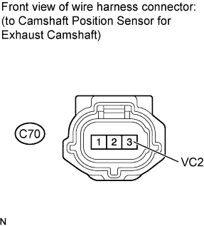

Turn the ignition switch on (IG).
Measure the voltage according to the value(s) in the table below.
- Standard voltage:
Tester Connection
Switch Condition
Specified Condition
C70-3 (VC2) - Body ground
Ignition switch on (IG)
4.5 to 5.0 V
Reconnect the camshaft position sensor (for exhaust camshaft) connector.
|
|
||||

| OK | |
|
| 3. CHECK HARNESS AND CONNECTOR (CAMSHAFT POSITION SENSOR - ECM) |
Disconnect the camshaft position sensor (for exhaust camshaft) connector.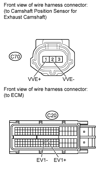
Disconnect the ECM connector.
Measure the resistance according to the value(s) in the table below.
- Standard resistance (Check for open):
Tester Connection
Condition
Specified Condition
C70-1 (VVE+) - C20-76 (EV1+)
Always
Below 1 Ω
C70-2 (VVE-) - C20-75 (EV1-)
Always
Below 1 Ω
- Standard resistance (Check for short):
Tester Connection
Condition
Specified Condition
C70-1 (VVE+) or C20-76 (EV1+) - Body ground
Always
10 kΩ or higher
C70-2 (VVE-) or C20-75 (EV1-) - Body ground
Always
10 kΩ or higher
Reconnect the camshaft position sensor (for exhaust camshaft) connector.
Reconnect the ECM connector.
|
|
||||
| OK | |
|
| 4. CHECK SENSOR INSTALLATION (CAMSHAFT POSITION SENSOR FOR EXHAUST CAMSHAFT) |
Check the camshaft position sensor (for exhaust camshaft) installation.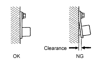
- OK:
- Sensor is installed correctly.
|
|
||||
| OK | |
|
| 5. INSPECT EXHAUST CAMSHAFT (TIMING ROTOR) |
Check the timing rotor of the exhaust camshaft.
- OK:
- Camshaft timing rotor does not have any cracks or deformation.
|
|
||||
| OK | |
|
| 6. REPLACE CAMSHAFT POSITION SENSOR (FOR EXHAUST CAMSHAFT) |
| NEXT | |
|
| 7. CHECK WHETHER DTC OUTPUT RECURS (DTC P0365, P0367 OR P0368) |
Connect an intelligent tester to the DLC3.
Turn the ignition switch on (IG).
Turn the tester on.
Select the following menu items: Powertrain / Engine and ECT / DTC / Clear.
Clear DTCs.
Start the engine and allow the engine to idle for 10 seconds or more.
Turn the ignition switch off.
Start the engine again and allow the engine to idle for 10 seconds or more.
Select the following menu items: Powertrain / Engine and ECT / DTC.
Read DTCs.
- Result:
Result
Proceed to
No output
A
P0365, P0367 or P0368
B
- HINT:
- If the engine does not start, replace the ECM.
|
|
||||
| A | |
|
| 8. ADJUST VALVE TIMING |
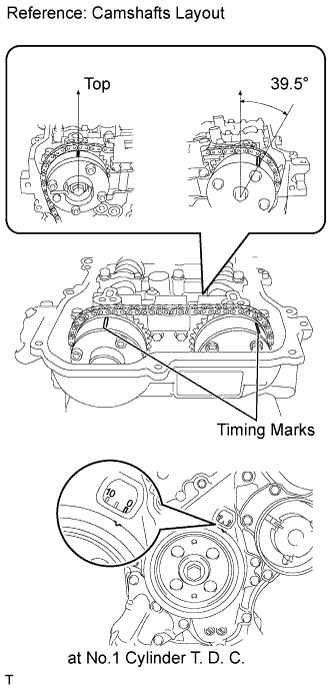 |
- HINT:
- There are no marks on the cylinder head to match-up for the purpose of checking valve timing. Valve timing can only be inspected by lining up the colored plates on the timing chain with the marks on the pulleys. It may be necessary to remove and re-install the chain to match up the timing marks (Click here).
| NEXT | |
|
| 9. CHECK WHETHER DTC OUTPUT RECURS (DTC P0365, P0367 OR P0368) |
Connect an intelligent tester to the DLC3.
Turn the ignition switch on (IG).
Turn the tester on.
Select the following menu items: Powertrain / Engine and ECT / DTC / Clear.
Clear DTCs.
Start the engine and allow the engine to idle for 10 seconds or more.
Turn the ignition switch off.
Start the engine again and allow the engine to idle for 10 seconds or more.
Select the following menu items: Powertrain / Engine and ECT / DTC.
Read DTCs.
- Result:
Result
Proceed to
No output
A
P0365, P0367 or P0368
B
- HINT:
- If the engine does not start, replace the ECM.
|
|
||||
| A | ||
 |
||
| ||
| 10. CHECK HARNESS AND CONNECTOR (CAMSHAFT POSITION SENSOR - ECM) |
Disconnect the camshaft position sensor (for exhaust camshaft) connector.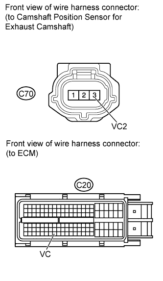
Disconnect the ECM connector.
Measure the resistance according to the value(s) in the table below.
- Standard resistance (Check for open):
Tester Connection
Condition
Specified Condition
C70-3 (VC2) - C20-117 (VC)
Always
Below 1 Ω
- Standard resistance (Check for short):
Tester Connection
Condition
Specified Condition
C70-3 (VC2) or C20-117 (VC) - Body ground
Always
10 kΩ or higher
Reconnect the camshaft position sensor (for exhaust camshaft) connector.
Reconnect the ECM connector.
|
|
||||
| OK | ||
|
||
| ||