Unable to Unlock Steering Wheel
Circuit diagnosis · Vehicles built from Aug 2005
WIRING DIAGRAM
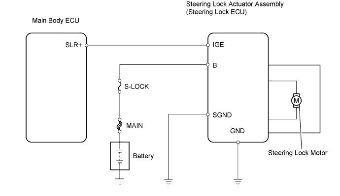

INSPECTION PROCEDURE
- HINT:
- Connect the intelligent tester to the DLC3 with the engine switch off, and turn any door courtesy switch ON and OFF at 1.5 second intervals until communication between the intelligent tester and the vehicle begins.
| 1. CHECK ENGINE SWITCH |

Check whether the engine switch can be turned on (IG) when the brake pedal is depressed.
- OK:
- Engine switch can be turned on (IG).
- HINT:
- If unable to turn the engine switch on (IG), inspect the engine immobiliser system (Click here ).
|
|
||||

| OK | |
 |
| 2. CHECK DTC |
Connect the intelligent tester to the DLC3.
Turn the engine switch on (IG) and turn the tester on.
Read the DTCs of the main body ECU by following the prompts displayed on the intelligent tester.
- OK:
- No DTCs related to main body ECU output.
|
|
||||
| OK | |
|
| 3. CHECK DTC |
Connect the intelligent tester to the DLC3.
Turn the engine switch on (IG) and turn the tester on.
Read the DTCs of the certification ECU by following the prompts displayed on the intelligent tester.
- OK:
- No DTCs related to certification ECU output.
|
|
||||
| OK | |
|
| 4. READ VALUE OF DATA LIST (LOCK/UNLOCK RECEIVE) |
Connect the intelligent tester to the DLC3.
Turn the engine switch on (IG) and turn the tester on.
Within 10 seconds of the engine switch being turned on (IG), check the Data List of the certification ECU by following the prompts displayed on the intelligent tester.
- Result:
Item
Measurement Item/
Range
Normal Condition
Lock / Unlock Receive
Steering lock command reception record/
YES or NO
YES: Steering lock / unlock signal received
NO: Steering lock / unlock signal not received
|
|
||||

| YES | |
|
| 5. INSPECT STEERING LOCK ACTUATOR ASSEMBLY (B POWER SOURCE - BODY GROUND) |
Disconnect the connector from the steering lock actuator assembly.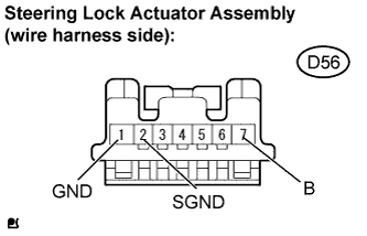
Measure the resistance.
- Standard resistance:
Tester Connection
Condition
Specified Condition
GND (D56-1) - Body ground
Always
Below 1 Ω
SGND (D56-2) - Body ground
Always
Below 1 Ω
- HINT:
- If there are any abnormalities, check for looseness at the ground point.
Measure the voltage.
- Standard voltage:
Tester Connection
Condition
Specified Condition
B (D56-7) - GND (D56-1)
Always
10 to 14 V
B (D56-7) - SGND (D56-2)
Always
10 to 14 V
Reconnect the connector.
|
|
||||
| OK | |
|
| 6. INSPECT STEERING LOCK ACTUATOR ASSEMBLY (IGE TERMINAL) |
Turn the engine switch on (IG) and immediately measure the voltage.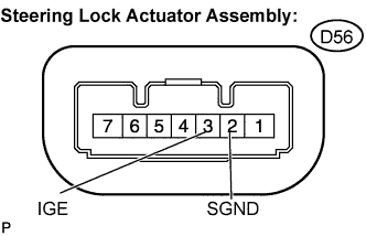
- Result:
Tester Connection
Result
Proceed to
IGE (D56-3) - SGND (D56-2)
Decreases to less than 1 V
A
IGE (D56-3) - SGND (D56-2)
Remains at 10 to 14 V
B
|
|
||||
| A | ||
 |
||
| ||
| 7. READ VALUE OF DATA LIST (S CODE CHECK) |
Connect the intelligent tester to the DLC3.
Turn the engine switch on (IG) and turn the tester on.
Check the Data List of the certification ECU by following the prompts displayed on the tester.
- Result:
Item
Measurement Item/
Range
Normal Condition
S Code Check
S code match record/
NG or OK
NG: S code not matched
OK: S code matched
|
|
||||
| NG | |
|
| 8. REPLACE ID CODE BOX |
Replace the ID code box with a normally functioning or new one.
Connect the intelligent tester to the DLC3.
Turn the engine switch on (IG) and turn the tester on.
Check the Data List of the certification ECU by following the prompts displayed on the tester.
- Result:
Item
Measurement Item/
Range
Normal Condition
S Code Check
S code match record/
NG or OK
NG: S code not matched
OK: S code matched
|
|
||||
| NG | ||
|
||
| ||
| 9. READ VALUE OF DATA LIST (L CODE CHECK) |
Connect the intelligent tester to the DLC3.
Turn the engine switch on (IG) and turn the tester on.
Check the Data List of the certification ECU by following the prompts displayed on the tester.
- Result:
Item
Measurement Item/
Range
Normal Condition
L Code Check
L code match record/
NG or OK
NG: L code not matched
OK: L code matched
|
|
||||
| NG | |
|
| 10. REPLACE ID CODE BOX |
Replace the ID code box with a normally functioning or new one.
Connect the intelligent tester to the DLC3.
Turn the engine switch on (IG) and turn the tester on.
Check the Data List of the certification ECU by following the prompts displayed on the tester.
- Result:
Item
Measurement Item/
Range
Normal Condition
L Code Check
L code match record/
NG or OK
NG: L code not matched
OK: L code matched
|
|
||||
| NG | ||
|
||
| ||
| 11. REPLACE STEERING LOCK ACTUATOR ASSEMBLY |
Replace the steering lock actuator with a normally functioning or new one.
Depress the brake pedal and then turn the engine switch on (IG).
Check whether the steering lock can be released by turning the steering wheel, and check that the engine starts.
- Standard:
- Steering lock is released and engine starts.
|
|
||||
| NG | ||
|
||
| ||