Headlight Signal Circuit
Circuit diagnosis · Vehicles built from Aug 2005
DESCRIPTION
The headlights are illuminated when the light control switch, located on the headlight dimmer switch, is turned to the HEAD position.For vehicles equipped with the daytime running light system, refer to the DRL Relay Circuit (Click here).
WIRING DIAGRAM
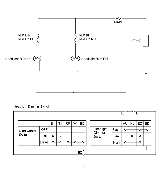

INSPECTION PROCEDURE
| 1. INSPECT FUSE (H-LP RH/H-LP LO RH, H-LP LH/H-LP LO LH) |

Remove the H-LP RH/H-LP LO RH and H-LP LH/H-LP LO LH fuses from the engine room relay block.
Measure the resistance.
- Standard resistance:
- Below 1 Ω
Reinstall the H-LP RH/H-LP LO RH and H-LP LH/H-LP LO LH fuses.
|
|
||||

| OK | |
 |
| 2. INSPECT BULB (HEADLIGHT BULB) |
Disconnect the B4 and B6 headlight connectors.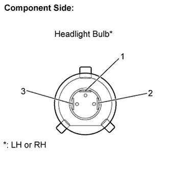
Apply battery voltage to the terminals and check that the headlight illuminates.
- Standard:
Measurement Condition
Standard
Positive battery - Terminal 1
Negative battery - Terminal 3
Headlight illuminates (HI-Beam)
Positive battery - Terminal 2
Negative battery - Terminal 3
Headlight illuminates (LO-Beam)
Reconnect the headlight connectors.
|
|
||||
| OK | |
|
| 3. CHECK HARNESS AND CONNECTOR (FUSE - HEADLIGHT) |
Disconnect the B4 and B6 headlight bulb connectors.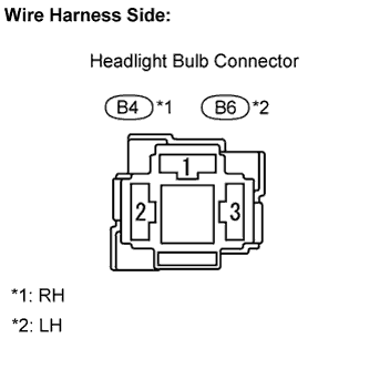
Measure the voltage.
- Standard voltage:
Tester Connection
Condition
Specified Condition
B4-3 - Body ground
Always
10 to 14 V
B6-3 - Body ground
Always
10 to 14 V
Reconnect the headlight bulb connectors.
|
|
||||
| OK | |
|
| 4. INSPECT HEADLIGHT DIMMER SWITCH |
Remove the headlight dimmer switch.
Inspect light control switch.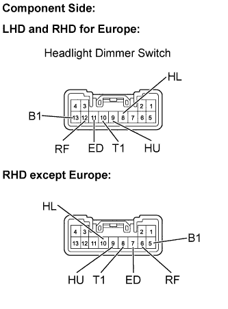
Measure the resistance.
- Standard resistance:
- LHD and RHD for Europe:
Tester Connection
Condition
Specified Condition
10 (T1) - 13 (B1)
TAIL
Below 1 Ω
10 (T1) - 13 (B1)
HEAD
Below 1 Ω
11 (ED) - 12 (RF)
HEAD
Below 1 Ω
- RHD except Europe:
Tester Connection
Condition
Specified Condition
5 (B1) - 8 (T1)
TAIL
Below 1 Ω
5 (B1) - 8 (T1)
HEAD
Below 1 Ω
6 (RF) - 7 (ED)
HEAD
Below 1 Ω
Inspect headlight dimmer switch.
Measure the resistance.
- Standard resistance:
- LHD and RHD for Europe:
Tester Connection
Condition
Specified Condition
9 (HU) - 11 (ED)
FLASH
Below 1 Ω
8 (HL) - 11 (ED)
LOW BEAM
Below 1 Ω
9 (HU) - 11 (ED)
HI BEAM
Below 1 Ω
- RHD except Europe:
Tester Connection
Condition
Specified Condition
7 (ED)- 9 (HU)
FLASH
Below 1 Ω
7 (ED) - 10 (HL)
LOW BEAM
Below 1 Ω
7 (ED) - 9 (HU)
HI BEAM
Below 1 Ω
Reinstall the headlight dimmer switch.
|
|
||||
| OK | |
|
| 5. CHECK HARNESS AND CONNECTOR (HEADLIGHT - HEADLIGHT DIMMER SWITCH) |
Disconnect the D4 headlight dimmer switch connector.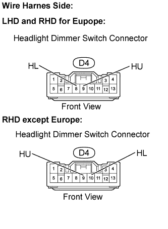
Measure the voltage.
- Standard voltage:
- LHD and RHD for Europe:
Tester Connection
Condition
Specified Condition
D4-8 (HL) - Body ground
Always
10 to 14 V
D4-9 (HU) - Body ground
Always
10 to 14 V
- RHD except Europe:
Tester Connection
Condition
Specified Condition
D4-9 (HU) - Body ground
Always
10 to 14 V
D4-10 (HL) - Body ground
Always
10 to 14 V
Reconnect the headlight dimmer switch connector.
|
|
||||
| OK | ||
 |
||
| ||