P0045 Turbocharger / Supercharger Boost Control Solenoid Circuit / Open
Diagnostic trouble codes · Vehicles built from Nov 2005
DESCRIPTION
The ECM optimizes the balance between the back pressure and boost pressure so that the balance is most appropriate for the engine speed and load, by performing two functions. It signals the VRV (Vacuum Regulating Valve) to open and close the variable nozzle vane that is built around the circumference of the turbine, and adjusts the flow rate and pressure of the exhaust gas that is input to the turbocharger.| DTC No. |
DTC Detection Conditions |
Trouble Areas |
| P0045 |
Open or short in VRV circuit for 3.0 seconds or more (The MIL is illuminated and a DTC is immediately set when a malfunction is detected) |
|
- HINT:
- DTC P0045 is set when the ignition switch is in the on (IG) position.
WIRING DIAGRAM
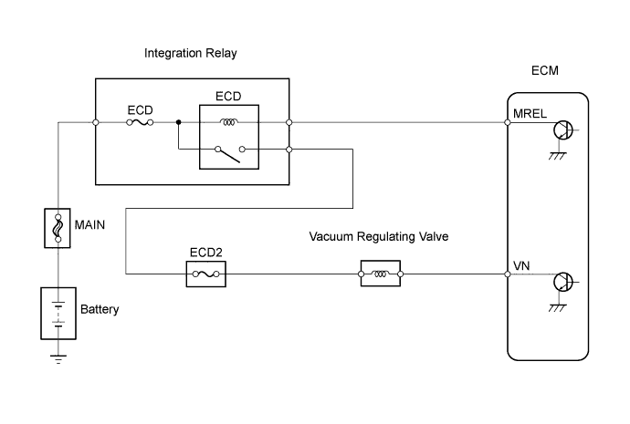

INSPECTION PROCEDURE
- HINT:
- Read freeze frame data using an intelligent tester. Freeze frame data record the engine condition when malfunctions are detected. When troubleshooting, freeze frame data can help determine if the vehicle was moving or stationary, if the engine was warmed up or not, if the air-fuel ratio was lean or rich, and other data, from the time the malfunction occurred.
| 1. CHECK FUSE (ECD2 FUSE) |

Remove the ECD2 fuse from the engine room relay block.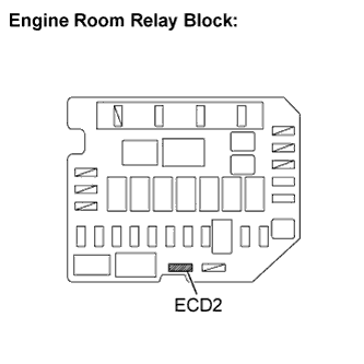
Check the ECD2 fuse resistance.
- Standard resistance:
- Below 1 Ω
Reinstall the ECD2 fuse.
|
|
||||

| OK | |
 |
| 2. INSPECT VACUUM REGULATING VALVE ASSEMBLY (OPERATION) |
Remove the vacuum regulating valve (Click here).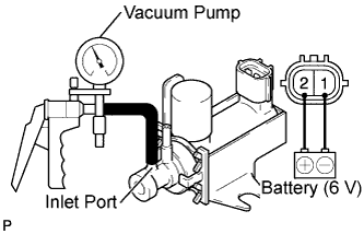
Apply 4 dry batteries of 1.5 V in series.
Check that the needle does not move when a vacuum is applied to the vacuum inlet port.
- OK:
- The VRV operates normally.
Reinstall the vacuum regulating valve (Click here).
|
|
||||
| OK | |
|
| 3. INSPECT VACUUM REGULATING VALVE ASSEMBLY (RESISTANCE) |
Remove the vacuum regulating valve (Click here).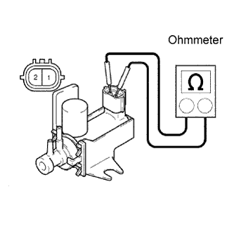
Measure the resistance between the terminals.
- Standard resistance:
Tester Connections
Specified Conditions
1 - 2
11 to 13 Ω at 20°C (68°F)
Check the resistance between each terminal and the body.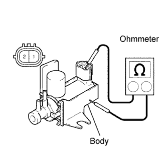
- Standard resistance:
Tester Connections
Specified Conditions
1 - Body
1 MΩ or higher
2 - Body
Reinstall the vacuum regulating valve (Click here).
|
|
||||
| OK | |
|
| 4. CHECK HARNESS AND CONNECTOR (VRV - ECM, VRV - ECD RELAY) |
Disconnect the C55 VRV connector.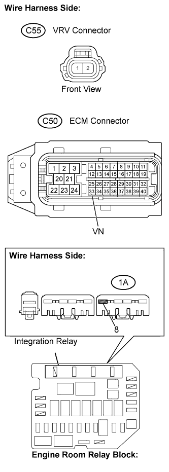
Disconnect the C50 ECM connector.
Remove the integration relay from the engine room relay block.
Check the resistance.
- Standard resistance (Check for open):
Tester Connections
Specified Conditions
VN (C50-33) - (C55-2)
Below 1 Ω
Integration relay (1A-8) - (C55-1)
- Standard resistance (Check for short):
Tester Connections
Specified Conditions
VN (C50-33) or (C55-2) - Body ground
10 kΩ or higher
Integration relay (1A-8) or (C55-1) - Body ground
Reconnect the VRV connector.
Reconnect the ECM connector.
Reinstall the integration relay.
|
|
||||
| NG | ||
 |
||
| ||