C0371/71 Yaw Rate Sensor (Test Mode DTC)
Diagnostic trouble codes · Vehicles built from Nov 2005
Also covers:
- C1232/32 Stuck in Deceleration Sensor
- C1234/34 Yaw Rate Sensor Malfunction
- C1279/79 Deceleration Sensor Output Voltage Malfunction (Test Mode DTC)
DESCRIPTION
The skid control ECU receives signals from the yaw rate and deceleration sensor via the CAN communication system.The yaw rate sensor has a built-in deceleration sensor.
If there is trouble in the bus lines between the yaw rate and deceleration sensor and the CAN communication system, DTC U0123/62 (malfunction in CAN communication with the yaw rate sensor) and U0124/69 (malfunction in CAN communication with the deceleration sensor) are output.
DTCs C0371/71 and C1279/79 are deleted when the yaw rate and deceleration sensor sends a yaw rate and/or deceleration signal or test mode ends. DTCs C0371/71 and C1279/79 are output only in test mode.
| DTC No. |
DTC Detecting Conditions |
Trouble Areas |
| C0371/71 |
Detected only during test mode |
|
| C1232/32 |
When any of following conditions detected:
|
|
| C1234/34 |
Sensor malfunction signal received from yaw rate sensor. |
|
| C1279/79 |
Detected only during test mode |
|
WIRING DIAGRAM
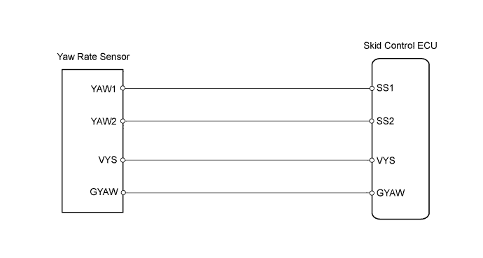

INSPECTION PROCEDURE
- HINT:
- When U0123/62, U0124/69 or U0126/63 is output together with C1232/32 or C1234/34, inspect and repair the trouble areas indicated by U0123/62, U0124/69 or U0126/63 first.
- NOTICE:
- When replacing the ABS and TRACTION actuator, perform zero point calibration (Click here).
| 1. CHECK DTC |

Clear the DTC(s) (Click here).
Turn the ignition switch off.
Turn the ignition switch on (IG) again and check that no CAN communication system DTC(s) is output.
Drive the vehicle at a speed of 30 km/h (19 mph) or more and check that no DTCs are output.
- Result:
Result
Proceed to
DTC output (relating to yaw rate and deceleration sensor)
A
DTC output (relating to CAN communication system)
B
DTC not output
C
|
|
||||
|
|
||||

| A | |
 |
| 2. CHECK YAW RATE SENSOR INSTALLATION |
Check that the yaw rate sensor has been installed correctly (Click here).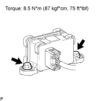
- OK:
- The sensor is tightened to the specified torque.
The sensor is not tilted.
- NOTICE:
- Do not use an electric impact wrench to tighten the yaw rate and deceleration sensor bolts because the sensor is sensitive to vibration.
|
|
||||
| OK | |
|
| 3. INSPECT YAW RATE SENSOR |
Remove the 2 bolts and the yaw rate sensor with the connector connected.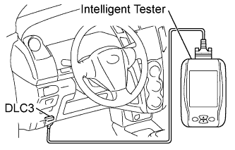
Connect the intelligent tester to the DLC3.
Turn the tester on.
Select the DATA LIST mode on the intelligent tester.Select the following menu items: Chassis / ABS/VSC/TRC / Data List.
DATA LIST: ABS/VSC/TRC Item (Display)
Measurement Item: Range (Display)
Normal Condition
Deceleration Sensor 2
Deceleration sensor reading:
min.: -18.52 m/s2, max.: 18.39 m/s2
min.: -18.52 m/s2
max.: 18.39 m/s2
Place the yaw rate sensor vertically to the ground and turn the sensor to the right and left.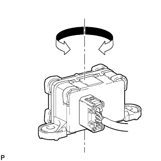
Check that the deceleration value of the deceleration sensor displayed on the intelligent tester changes.
- OK:
- Deceleration value changes.
|
|
||||
| OK | |
|
| 4. CHECK YAW RATE SENSOR TERMINAL VOLTAGE |
Disconnect the yaw rate sensor connector.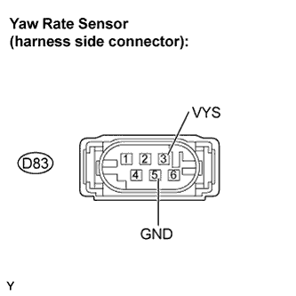
Turn the ignition switch on (IG).
Measure the voltage.
- Standard Voltage:
Tester Connection
Specified Condition
D83-3 (VYS) - D83-5 (GND)
10 to 14 V
Measure the resistance.
- Standard Resistance:
Tester Connection
Specified Condition
D83-5 (GND) - Body ground
Below 1 Ω
|
|
||||
| OK | ||
 |
||
| ||