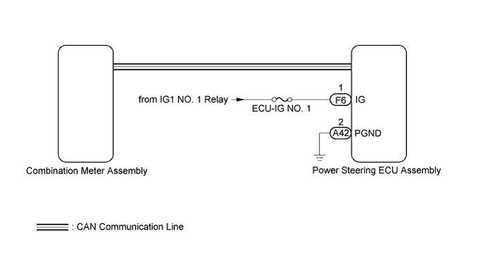
POWER STEERING SYSTEM > PS Warning Light Remains ON |
| 1.CHECK HARNESS AND CONNECTOR |
Turn the ignition switch to ON.
Check the indication condition of the EPS warning light by wiggling the power steering ECU assembly connector and wire harness up and down, and right and left.
|
| ||||
| OK | |
 |
| 2.CHECK CAN COMMUNICATION SYSTEM |
Check for DTCs of the CAN communication system.
| Yaw Rate Sensor Type | See Page |
| except Separate Type Yaw Rate Sensor |
Click here
|
| for Separate Type Yaw Rate Sensor |
Click here
|
| Result | Proceed to |
| DTCs is not output | A |
| DTCs is output (except Separate Type Yaw Rate Sensor) | B |
| DTCs is output (for Separate Type Yaw Rate Sensor) | C |
|
| ||||
|
| ||||
| A | |
|
| 3.CHECK HARNESS AND CONNECTOR (POWER STEERING ECU ASSEMBLY - BATTERY AND BODY GROUND) |
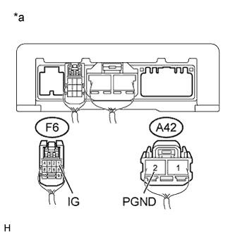 |
Disconnect the power steering ECU assembly connectors.
Measure the voltage according to the value(s) in the table below.
| Tester Connection | Switch Condition | Specified Condition |
| F6-1 (IG) - Body ground | Ignition switch ON | 11 to 14 V |
Measure the resistance according to the value(s) in the table below.
| Tester Connection | Condition | Specified Condition |
| A42-2 (PGND) - Body ground | Always | Below 1 Ω |
| *a | Rear view of wire harness connector (to Power Steering ECU Assembly) |
|
| ||||
| A | |
|
| 4.REPLACE POWER STEERING ECU ASSEMBLY |
Replace the power steering ECU assembly.
| NEXT | |
|
| 5.PERFORM ASSIST MAP WRITING |
Perform assist map writing (Click here).
| NEXT | |
|
| 6.CHECK EPS WARNING LIGHT |
Check that the EPS warning light on the combination meter assembly does not come on.
|
| ||||
| OK | ||
 | ||
| ||
