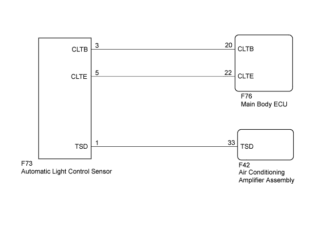
DTC B14A2 Driver Side Solar Sensor Short Circuit |
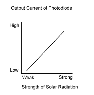
| DTC No. | DTC Detection Condition | Trouble Area |
| B14A2 | A short in the driver side solar sensor circuit. |
|
| 1.READ VALUE USING INTELLIGENT TESTER |
Connect the intelligent tester to the DLC3.
Turn the ignition switch to ON.
Turn the intelligent tester on.
Enter the following menus: Body / Air Conditioner / Data List.
According to the display on the intelligent tester, read the Data List.
| Tester Display | Measurement Item/Range | Normal Condition | Diagnostic Note |
| Solar Sensor (D side) | Driver side solar sensor / Min.: 0 Max.: 255 | Driver side solar sensor value increases as brightness increases | - |
| Result | Proceed to |
| OK (When troubleshooting according to the DTC) | A |
| OK (When troubleshooting according to Problem Symptoms Table) | B |
| NG | C |
|
| ||||
|
| ||||
| A | |
 |
| 2.CHECK FOR DTC |
Clear the DTCs (Click here).
Check for DTCs (Click here).
|
| ||||
| OK | ||
 | ||
| ||
| 3.CHECK HARNESS AND CONNECTOR (POWER SOURCE CIRCUIT) |
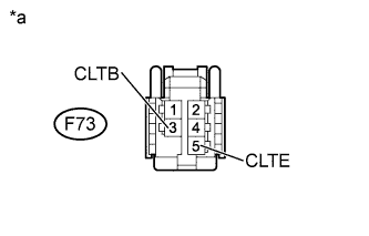 |
Disconnect the F73 automatic light control sensor connector.
Measure the voltage according to the value(s) in the table below.
| Tester Connection | Switch Condition | Specified Condition |
| F73-3 (CLTB) - F73-5 (CLTE) | Ignition switch off | Below 1 V |
| F73-3 (CLTB) - F73-5 (CLTE) | Ignition switch ON | 11 to 14 V |
| *a | Front view of wire harness connector (to Automatic Light Control Sensor) |
|
| ||||
| OK | |
|
| 4.CHECK HARNESS AND CONNECTOR (AUTOMATIC LIGHT CONTROL SENSOR - AIR CONDITIONING AMPLIFIER ASSEMBLY) |
Disconnect the F73 automatic light control sensor connector.
Disconnect the F42 air conditioning amplifier assembly connector.
Measure the resistance according to the value(s) in the table below.
| Tester Connection | Condition | Specified Condition |
| F73-1 (TSD) - F42-33 (TSD) | Always | Below 1 Ω |
| F73-1 (TSD) - Body ground | Always | 10 kΩ or higher |
|
| ||||
| OK | |
|
| 5.CHECK AUTOMATIC LIGHT CONTROL SENSOR |
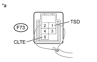 |
Remove the automatic light control sensor (Click here).
Reconnect the automatic light control sensor connector.
Reconnect the air conditioning amplifier assembly connector.
Measure the voltage according to the value(s) in the table below.
| Tester Connection | Switch Condition | Specified Condition |
| F73-1 (TSD) - F73-5 (CLTE) | Ignition switch ON Sensor subjected to electric light | 0.8 to 4.3 V |
| F73-1 (TSD) - F73-5 (CLTE) | Ignition switch ON Sensor covered with cloth | Below 0.8 V |
| *a | Component with harness connected (Automatic Light Control Sensor) |
|
| ||||
| OK | ||
| ||
| ||
| 6.CHECK HARNESS AND CONNECTOR (AUTOMATIC LIGHT CONTROL SENSOR - MAIN BODY ECU) |
Disconnect the F73 automatic light control sensor connector.
Disconnect the F76 main body ECU connector.
Measure the resistance according to the value(s) in the table below.
| Tester Connection | Condition | Specified Condition |
| F73-3 (CLTB) - F76-20 (CLTB) | Always | Below 1 Ω |
| F73-5 (CLTE) - F76-22 (CLTE) | Always | Below 1 Ω |
| F73-3 (CLTB) - Body ground | Always | 10 kΩ or higher |
| F73-5 (CLTE) - Body ground | Always | 10 kΩ or higher |
|
| ||||
| OK | ||
| ||
| ||

