LIFTGATE
REMOVAL
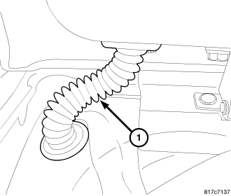
1. Open liftgate.
2. Disconnect washer hose.
3. Disconnect liftgate harness (1).
4. Disconnect cable from handle.
5. Support the liftgate and disconnect the liftgate prop cylinders, (Refer to 23 - BODY/LIFTGATE/PROP ASSEMBLY - REMOVAL)
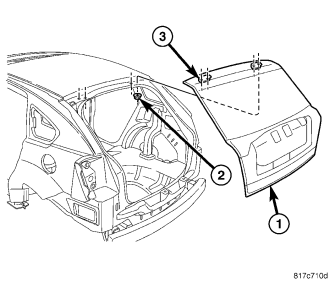
6. Remove fasteners (2) attaching liftgate (1) to liftgate hinge (3).
INSTALLATION
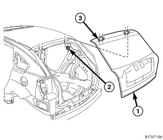
1. With the help of an assistant, place liftgate (1) onto liftgate hinges (3).
2. Torque nuts (2) to 15 N·m (11 ft. lbs.).
3. Install the liftgate prop cylinders, (Refer to 23 - BODY/LIFTGATE/PROP - INSTALLATION)
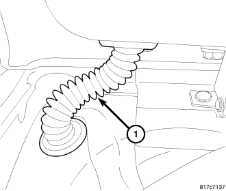
4. Install liftgate harness (1).
5. Install washer hose.
6. Adjust liftgate, (Refer to 23 - BODY/LIFTGATE/LIFTGATE - ADJUSTMENTS).
ADJUSTMENTS
NOTE: The position of the liftgate can be adjusted upward or downward by the use of slots in the hinge. An inward or outward adjustment is achieved by use of slots in the body. If an inward or outward adjustment is needed, use a body sealer on the hinge to body mating surface.
In/out
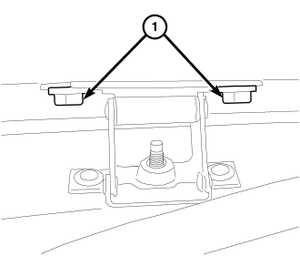
1. Using a trim stick C-4755 or equivalent, remove the upper rear headliner trim.
2. For the upper lift gate in/out adjustments, loosen the two hinge to header bolts and four nuts and adjust to specifications (Refer to 23 - BODY/BODY STRUCTURE/GAP AND FLUSH - SPECIFICATIONS).
3. Tighten the hinge bolts to 15 N·m (11 ft. lbs.).
4. Position the headliner back into place and seat the push pin fasteners fully.
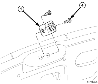
5. Remove the liftgate scuff plate, (Refer to 23 - BODY/INTERIOR/PLATE - LIFTGATE SCUFF - REMOVAL).
6. For the lower lift gate adjustments, loosen the striker screws (4) and adjust to specifications (Refer to 23 - BODY/BODY STRUCTURE/GAP AND FLUSH - SPECIFICATIONS)
7. Tighten the striker screws to 23 N·m (17 ft. lbs.).
8. Install the liftgate scuff plate, (Refer to 23 - BODY/INTERIOR/PLATE - LIFTGATE SCUFF - INSTALLATION).
9. Position the upper rear headliner trim and seat fully.
Up/Down and Left/Right
1. Loosen the hinge to liftgate bolts (1).
2. Remove the liftgate scuff plate, (Refer to 23 - BODY/INTERIOR/PLATE - LIFTGATE SCUFF - REMOVAL).
3. Loosen the striker screws (4).
4. Adjust the liftgate up/down position and tighten the hinge bolts to 15 N·m (11 ft. lbs.). (Refer to 23 - BODY/BODY STRUCTURE/GAP AND FLUSH - SPECIFICATIONS)
5. Confirm the lower liftgate in/out position and tighten the striker screws to 23 N·m (17 ft. lbs.).
6. Install the liftgate scuff plate, (Refer to 23 - BODY/INTERIOR/PLATE - LIFTGATE SCUFF - INSTALLATION).