LOWER BALL JOINT
DIAGNOSIS AND TESTING - LOWER BALL JOINT
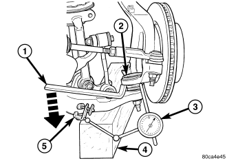
1. Raise the vehicle on a drive-on hoist.
NOTE: If a drive-on hoist is not available, use wooden blocks with jack stands to support the lower control arm in the ball joint area. Place the jack stands appropriately and lower the hoist placing weight on the lower control arm. The lower control arms should now be supporting the vehicle weight.
2. With the use of jack stands, lift the front end off the hoist and position wooden blocks (4) underneath both lower control arms supporting the vehicles weight.
3. Remove the tire and wheel assembly.
4. Attach a dial indicator (3) to the base of the lower control arm and align the dial indicator's contact point with the direction of the stud axis, touch the machined flat on the knuckle and zero the dial indicator.
NOTE: Use care when applying the load to the knuckle, so the parts are not damaged using care not to tear the boot.
5. From the front of the vehicle, insert a pry bar (1) to get it rested on the lower control arm and use lever principle to push the knuckle up until the arm of the dial indicator no longer moves.
6. Record the ball joint (2) movement on each side of the vehicle. The end play is acceptable with no more than 1.5mm of end play back to back.
REMOVAL
1. Remove the tire and wheel assembly.
2. Remove the brake caliper and rotor (Refer to 5 - BRAKES/HYDRAULIC/MECHANICAL/ROTORS - REMOVAL).
3. Disconnect the tie rod from the steering knuckle (Refer to 19 - STEERING/LINKAGE/TIE ROD END - REMOVAL).
4. Remove the steering knuckle (Refer to 2 - SUSPENSION/FRONT/KNUCKLE - REMOVAL).
5. Move the halfshaft to the side and support the halfshaft out of the way (If Equipped).
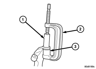
NOTE: Extreme pressure lubrication must be used on the threaded portions of the tool. This will increase the longevity of the tool and insure proper operation during the removal and installation process .
6. Secure the steering knuckle in a vise.
7. Remove the ball joint boot.
8. Press the ball joint from the steering knuckle using special tools C-4212–F (PRESS)(2), 8859-2 (RECEIVER)(3) and 8859-1 (DRIVER)(1) .
INSTALLATION
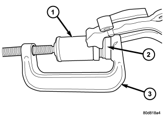
NOTE: Extreme pressure lubrication must be used on the threaded portions of the tool. This will increase the longevity of the tool and insure proper operation during the removal and installation process .
NOTE: The plastic shipping cover must be in place over the ball joint boot while pressing the ball joint into the knuckle.
1. Install the ball joint into the steering knuckle and press in using special tools C-4212–F (press)(3), 8859-3 (driver)(2) and 6761 (receiver)(1) .
2. Remove the support for the halfshaft and install into position (If Equipped).
3. Install the steering knuckle (Refer to 2 - SUSPENSION/FRONT/KNUCKLE - INSTALLATION).
4. Install the tie rod end into the steering knuckle (Refer to 19 - STEERING/LINKAGE/TIE ROD END - INSTALLATION).
5. Install and tighten the halfshaft nut to 136 N·m (100 ft. lbs.).
6. Install the brake caliper and rotor (Refer to 5 - BRAKES/HYDRAULIC/MECHANICAL/ROTORS - INSTALLATION).
7. Install the tire and wheel assembly (Refer to 22 - TIRES/WHEELS/WHEELS - STANDARD PROCEDURE).
8. Check the vehicle ride height (Refer to 2 - SUSPENSION/WHEEL ALIGNMENT - STANDARD PROCEDURE).
9. Perform a wheel alignment (Refer to 2 - SUSPENSION/WHEEL ALIGNMENT - STANDARD PROCEDURE).