CAMSHAFT(S)
DESCRIPTION
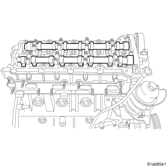
The camshafts are made of gray cast iron with eight machined lobes and four bearing journals..
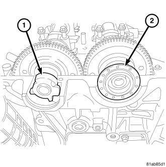
1. The exhaust camshaft (1) incorporates the CMP sensor wheel.
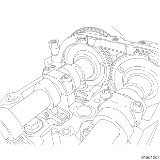
2. The dots on the back of the camshaft gears are for initial timing only. These dots are for timing the camshafts to each other. To correctly set engine timing, the camshafts must be set to 90° ATDC. The camshaft locking tool is used to correctly set the camshafts to their proper location.
REMOVAL - CAMSHAFTS
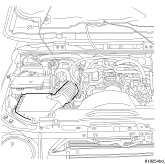
1. Disconnect negative battery cable.
2. Remove engine cover. (Refer to 9 - ENGINE - REMOVAL).
3. Remove accessory drive belt (Refer to 7 - COOLING/ACCESSORY DRIVE/DRIVE BELTS - REMOVAL).
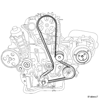
4. Rotate the engine to 90 degrees ATDC and install special tool VM.9992. (Refer to 9 - ENGINE/VALVE TIMING - STANDARD PROCEDURE).
CAUTION: Before removing the cylinder head cover/intake manifold or timing belt the engine must rotated to the 90° ATDC. The camshafts and the crankshaft must all be set to the correct position. Failure to do so could result in valve and/or piston damage during reassembly. (Refer to 9 - ENGINE/VALVE TIMING - STANDARD PROCEDURE)
5. Remove timing belt (Refer to 9 - ENGINE/VALVE TIMING/TIMING BELT/CHAIN AND SPROCKETS - REMOVAL).
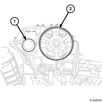
6. Remove the camshaft sprocket (2).
7. Remove the exhaust camshaft oil seal (1).
8. Remove the intake camshaft oil seal (2).
9. Using a circular pattern, loosen the camshaft caps.
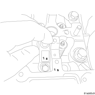
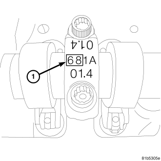
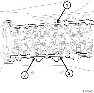
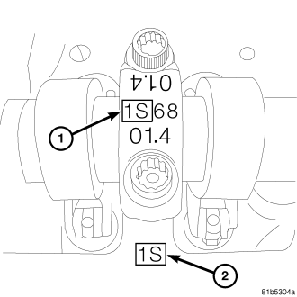
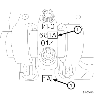
NOTE: The camshaft caps must be installed in the same location and direction as they were removed. Match the marks on the camshaft cap to the marks on the cylinder head.
10. Remove the camshaft caps.
11. Remove the camshafts.
INSTALLATION - CAMSHAFTS
1. Lubricate the camshaft journals with Mopar® Engine Oil Supplement, or equivalent.
2. Make sure that the timing marks on the back side of the camshafts are horizontal and facing each other.
3. Carefully install camshafts onto the camshaft journals.
NOTE: The dots on the back of the camshaft gears are for initial timing only. These dots are for timing the camshafts to each other. To correctly set engine timing, the camshafts must be set to 90° ATDC. The camshaft locking tool is used to correctly set the camshafts to their proper location.
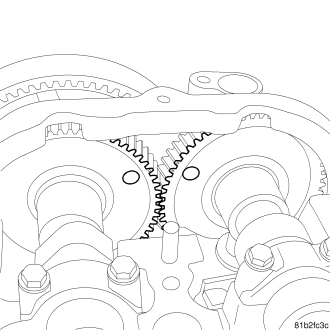
4. Rotate the camshafts so that the camshaft locking tool fits into place.
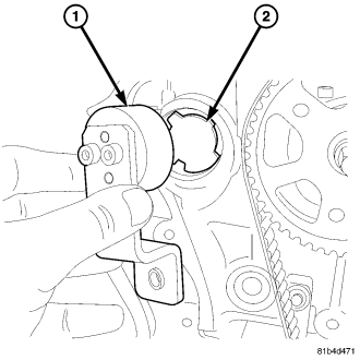
5. Install the camshaft locking tool.
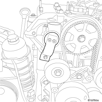
6. When the camshaft locking tool is bolted in place, the camshafts are locked at 90° ATDC.
7. Install the intake camshaft oil seal (2).
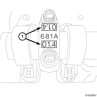
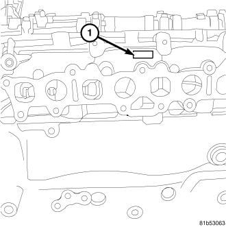
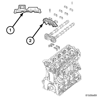
8. Use a thin bead of Loctite 510 to the front camshaft cap (2) in the location illustrated (1).
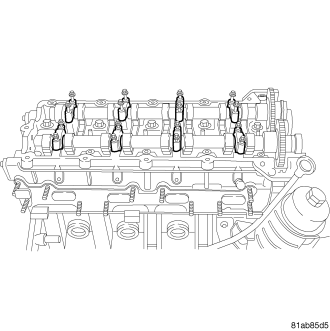
9. Loosely install the camshaft bolts finger tight.
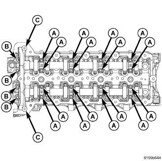
NOTE: When the camshaft caps are removed, always replace the camshaft cap bolts.
10. The camshaft bolts have 3 different bolt sizes.
- Bolts A are M6 35
- Bolts B are M6 45
- Bolts C are M6 stud bolts.
11. Put a thin bead of silicone on the front camshaft cap (the cap that are secured by bolts “b”).
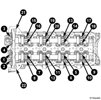
12. Following the illustrated pattern, torque the camshaft cap bolts to 11 Nm (98 lbs. in.).
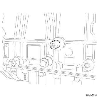
13. Make sure the crankshaft locking tool is in place.
14. Install the timing belt. (Refer to 9 - ENGINE/VALVE TIMING/TMNG BELT/CHAIN TENSIONER&PULLEY - INSTALLATION)
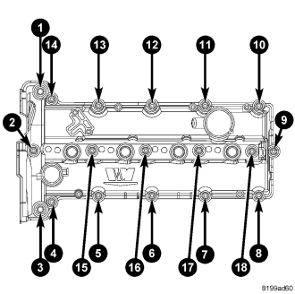
15. Install the cylinder head cover. (Refer to 9 - ENGINE/CYLINDER HEAD/CYLINDER HEAD COVER(S) - INSTALLATION)
CHECKING CAMSHAFT ENDPLAY
1. After camshafts are properly installed in cylinder head cover check end play of camshafts with a dial indicator. The end play should be between 0.10 mm - 0.55 mm .
NOTE: If the camshaft endplay is not within specification, replace the cylinder head.
2. Measure the camshaft end play with a dial indicator. The end play should be between 0.15 mm 0.35 mm (0.006 in — 0.0138 in.).