HUB / BEARING
DESCRIPTION
The bearing used on the front hub of this vehicle is the combined hub and bearing unit type assembly. This unit assembly combines the front wheel mounting hub (flange) and the front wheel bearing into a one piece unit. The wheel mounting studs are the only replaceable component of the hub/bearing assembly.OPERATION
The hub/bearing assembly is mounted to the steering knuckle and is retained by three mounting bolts accessible from the back of the steering knuckle. The hub/bearing unit is not serviceable and must be replaced as an assembly if the bearing or the hub is determined to be defective.REMOVAL
1. Raise and support the vehicle.
2. Remove the wheel and tire assembly. Support the caliper, Do not let the caliper hang by the hose.
3. Remove the disc brake caliper (1) (Refer to 5 - BRAKES/HYDRAULIC/MECHANICAL/DISC BRAKE CALIPERS - REMOVAL).
4. Remove the brake caliper adaptor (1) (Refer to 5 - BRAKES/HYDRAULIC/MECHANICAL/DISC BRAKE CALIPER ADAPTER - REMOVAL).
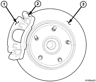
5. Remove the disc brake rotor (3) (Refer to 5 - BRAKES/HYDRAULIC/MECHANICAL/ROTORS - REMOVAL).
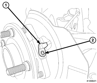
6. Remove the wheel speed sensor bolt (2).
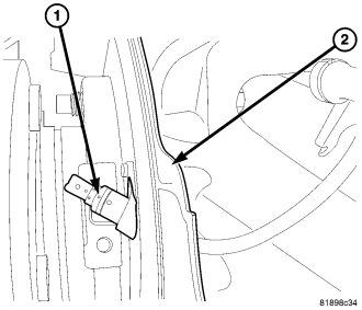
7. Remove the wheel speed sensor (1) through the hole in the brake shield (2) (Refer to 5 - BRAKES/ELECTRICAL/FRONT WHEEL SPEED SENSOR - REMOVAL).
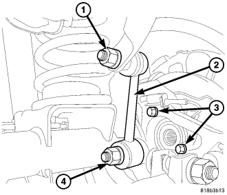
8. Remove the axle shaft nut if equipped.
9. Remove the 3 hub bearing mounting bolts (3) from the back of the steering knuckle. Remove hub bearing from the steering knuckle.
INSTALLATION
1. Install the hub bearing to the knuckle.
2. Install the hub bearing to knuckle and the 3 bolts (3) then tighten to 102 N·m (75 ft. lbs.).
3. Install the axle nut if equipped. Tighten to 136 N·m (100 ft. lbs.).
4. Install the wheel speed sensor (1) through the hole in the brake shield (2) (Refer to 5 - BRAKES/ELECTRICAL/FRONT WHEEL SPEED SENSOR - INSTALLATION).
5. Install the wheel speed sensor (1) into the hub & bearing and install the mounting bolt (2). Tighten to 4-6 N·m (34-50 in. lbs.).
6. Install the brake rotor (3) (Refer to 5 - BRAKES/HYDRAULIC/MECHANICAL/ROTORS - INSTALLATION).
7. Install the brake caliper adaptor (1) (Refer to 5 - BRAKES/HYDRAULIC/MECHANICAL/DISC BRAKE CALIPER ADAPTER - INSTALLATION).
8. Install the caliper (1) (Refer to 5 - BRAKES/HYDRAULIC/MECHANICAL/DISC BRAKE CALIPERS - INSTALLATION).
9. Install the wheel and tire assembly (Refer to 22 - TIRES/WHEELS - STANDARD PROCEDURE).
10. Remove the support and lower the vehicle.