INSTALLATION
HOUSING-AIR DISTRIBUTION
NOTE: LHD model with A/C shown in illustrations. RHD and heater-only models similar.
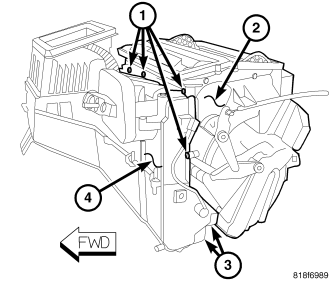
1. Position the air distribution housing (2) onto the rear of the HVAC housing (4).
2. Install the two metal retaining clips (3) that secure the bottom of the air distribution housing to the HVAC housing.
3. Install the seven screws (1) that secure the air distribution housing to the HVAC housing. Tighten the screws to 1.2 N·m (10 in. lbs.).
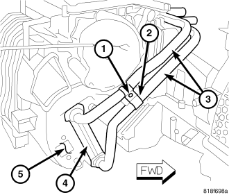
NOTE: If the foam seals for the heater core are deformed or damaged, they must be replaced.
4. Carefully install the heater core (4) into the passenger side of the air distribution housing (5).
5. Install the retaining bracket (2) and the screw (1) that secures the heater core tubes (3) to the air distribution housing. Tighten the screw to 1.2 N·m (10 in. lbs.)
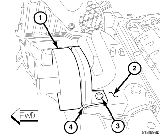
6. Position the flange (4) to the front of the HVAC housing (2).
7. Install the screw (3) that secures the flange to the HVAC housing. Tighten the screw to 1.2 N·m (10 in. lbs.).
NOTE: If the foam seal for the flange is deformed or damaged, it must be replaced.
8. Install the foam seal (1) onto the flange.
9. Install the floor distribution ducts onto the air distribution housing (refer to 24 - HEATING & AIR CONDITIONING/DISTRIBUTION/DUCTS-FLOOR DISTRIBUTION - INSTALLATION).
NOTE: If the heater core is being replaced, flush the cooling system (refer to 7 - COOLING - STANDARD PROCEDURE - COOLING SYSTEM CLEANING/REVERSE FLUSHING).
10. Install the HVAC housing assembly (refer to 24 - HEATING & AIR CONDITIONING/DISTRIBUTION/HOUSING-HVAC - HOUSING-HVAC ASSEMBLY - INSTALLATION).
HOUSING-AIR INLET
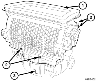
NOTE: LHD model shown. RHD model similar.
1. Position the air inlet housing (1) onto the top of the HVAC housing (3).
2. Install the four screws (2) that secure the air inlet housing to the HVAC housing. Tighten the screws to 1.2 N·m (10 in. lbs.).
NOTE: If the foam seal on the top of the inlet housing is deformed or damaged, the seal must be replaced.
3. Install the HVAC housing assembly (refer to 24 - HEATING & AIR CONDITIONING/DISTRIBUTION/HOUSING-HVAC - HOUSING-HVAC ASSEMBLY - INSTALLATION).
SCREEN-AIR INLET
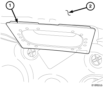
NOTE: LHD model shown. RHD model similar.
1. Position the air inlet screen (1) to the passenger compartment side of the cowl panel (2) and engage the retaining tabs that secure the screen to the cowl. Make sure the retaining tabs are fully engaged.
NOTE: Make sure the air inlet screen retaining tabs are fully engaged. Failure to fully engage the screen to the cowl and dash panel will result in a leak.
2. Push the air inlet screen upward to engage the retaining tabs that secure the screen to the dash panel. Make sure the retaining tabs are fully engaged.
3. Install the HVAC housing assembly (refer to 24 - HEATING & AIR CONDITIONING/DISTRIBUTION/HOUSING-HVAC - HOUSING-HVAC ASSEMBLY - INSTALLATION).
HOUSING-HVAC
NOTE: LHD model shown in illustrations. RHD model similar.
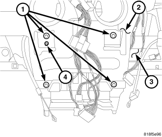
1. Position the HVAC housing assembly (3) into the instrument panel support (2). Be certain that the housing alignment pin (4) is correctly located.
2. Install the four bolts (1) that secure the HVAC housing assembly to the center of instrument panel support. Tighten the bolts to 4 N·m (35 in. lbs.).
NOTE: If a foam seal on the top of the HVAC housing is deformed or damaged, the seal must be replaced.
3. Install the instrument panel ducts (refer to 24 - HEATING & AIR CONDITIONING/DISTRIBUTION/DUCTS-INSTRUMENT PANEL - INSTALLATION).
4. Install the defroster duct (refer to 24 - HEATING & AIR CONDITIONING/DISTRIBUTION/DUCT-DEFROSTER - INSTALLATION).
5. Install the demister ducts (refer to 24 - HEATING & AIR CONDITIONING/DISTRIBUTION/DUCTS-INSTRUMENT PANEL DEMISTER - INSTALLATION).
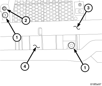
6. Verify that the housing alignment pin (2) is correctly located in the passenger side of the instrument panel support (3).
7. Install the two bolts (1) that secure the air inlet housing (4) to the instrument panel support. Tighten the bolts to 4 N·m (35 in. lbs.).
8. Connect the instrument panel wire harness connectors to the evaporator temperature sensor, blower motor resistor, blower motor and the recirculation door actuator.
9. Install the instrument panel cover (refer to 23 - BODY/INSTRUMENT PANEL/INSTRUMENT PANEL COVER - INSTALLATION).
10. Install the instrument panel (refer to 23 - BODY/INSTRUMENT PANEL/INSTRUMENT PANEL ASSEMBLY - INSTALLATION).
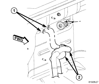
11. Remove the previously installed plugs or caps and connect the heater hoses (2) to the heater core tubes (1).
12. Using cable-type spring clamp pliers or equivalent, correctly position the two hose clamps that secure the heater hoses to the heater core tubes and engage the clamps to the tubes.
13. If equipped with the 3.8L engine, install the upper intake manifold (refer to 9 - ENGINE/MANIFOLDS/MANIFOLD-INTAKE-UPPER - INSTALLATION).
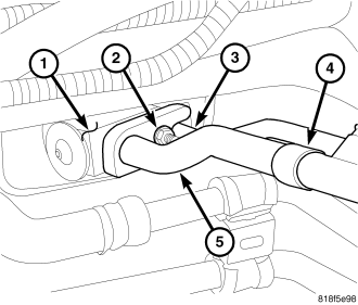
14. Remove the tape or plugs from the opened refrigerant line fittings and the expansion valve ports.
15. Lubricate new O-ring seals with clean refrigerant oil and install them onto the refrigerant line fittings. Use only the specified O-rings as they are made of special materials compatible to the R-134a system. Use only refrigerant oil of the type recommended for the A/C compressor in the vehicle.
16. Connect the A/C liquid line (3) and A/C suction line (5) onto the A/C expansion valve (1).
17. Install the nut (2) that secures the A/C liquid and suction lines to the A/C expansion valve. Tighten the nut to 8 N·m (70 in. lbs.).
18. Reconnect the negative battery cable.
19. If the heater core is being replaced, flush the cooling system (refer to 7 - COOLING - STANDARD PROCEDURE - COOLING SYSTEM CLEANING/REVERSE FLUSHING).
20. Refill the engine cooling system (refer to 7 - COOLING/ENGINE - STANDARD PROCEDURE - COOLING SYSTEM FILL).
21. Evacuate the refrigerant system (refer to 24 - HEATING & AIR CONDITIONING/PLUMBING - STANDARD PROCEDURE - REFRIGERANT SYSTEM EVACUATE).
22. Charge the refrigerant system (refer to 24 - HEATING & AIR CONDITIONING/PLUMBING - STANDARD PROCEDURE - REFRIGERANT SYSTEM CHARGE).