REMOVAL
Removal / installation
| 1. REMOVE COOL AIR INTAKE DUCT SEAL |

Remove the 11 clips and intake duct seal.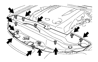

| 2. REMOVE ENGINE ROOM SIDE COVER LH |
Remove the 5 clips and side cover.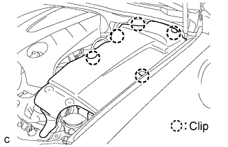
| 3. REMOVE ENGINE ROOM SIDE COVER RH |
Remove the 2 clips and side cover.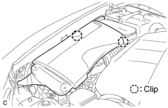
| 4. REMOVE V-BANK COVER SUB-ASSEMBLY |
Raise the V-bank cover to disengage the clip on the rear of the cover. Raise the cover again to disengage the 2 clips on the front of the cover and remove the cover.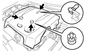
- NOTICE:
- Attempting to disengage both front and rear clips at the same time may cause the cover to break.
| 5. DISCHARGE REFRIGERANT FROM REFRIGERATION SYSTEM |
Start up the engine.
Turn the A/C switch on.
Operate the cooler compressor at an engine rpm of approximately 1,000 for 5 to 6 minutes to circulate the refrigerant and collect compressor oil remaining in each component into the cooler compressor as much as possible.
Stop the engine.
Using SST, let the refrigerant gas out.
- SST
- 07110-58060
(07117-58060, 07117-58070, 07117-58080, 07117-58090, 07117-78050, 07117-88060, 07117-88070, 07117-88080)
| 6. DISCHARGE FUEL SYSTEM PRESSURE |
| 7. PLACE FRONT WHEELS FACING STRAIGHT AHEAD |
| 8. DISCONNECT CABLE FROM NEGATIVE BATTERY TERMINAL |
| 9. REMOVE FRONT WHEEL |
| 10. REMOVE ENGINE UNDER COVER |
| 11. REMOVE NO. 2 ENGINE UNDER COVER |
| 12. REMOVE ENGINE UNDER COVER REAR LH |
Remove the bolt and engine under cover LH.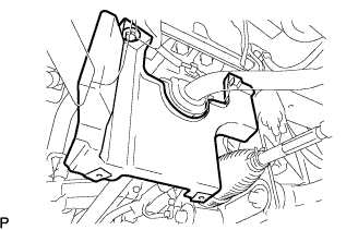
| 13. REMOVE ENGINE UNDER COVER REAR RH |
- HINT:
- Remove the RH side following the same procedures as with the LH side.
| 14. DRAIN ENGINE OIL |
Remove the drain plug.
Install a new gasket and the drain plug.
- Torque:
- 40 N*m{ 408 kgf*cm , 30 ft.*lbf }
| 15. DRAIN ENGINE COOLANT |
- NOTICE:
- Do not remove the radiator cap while the engine and radiator are still hot. Pressurized, hot engine coolant and steam may be released and cause serious burns.
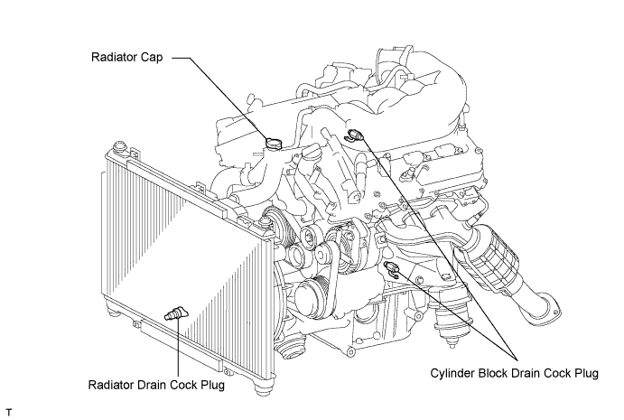
Remove the radiator cap and reservoir tank cap.
Loosen the radiator drain cock plug and 2 cylinder block drain cock plugs. Then drain the coolant.
- HINT:
- Collect the coolant in a container and dispose of it according to the regulations in your area.
| 16. REMOVE FRONT EXHAUST PIPE ASSEMBLY |
| 17. REMOVE PROPELLER SHAFT WITH CENTER BEARING ASSEMBLY |
| 18. REMOVE NO. 1 INLET AIR CLEANER |
Remove the bolt, clip and inlet air cleaner.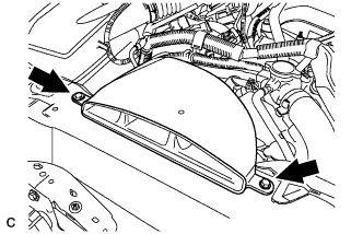
| 19. REMOVE AIR CLEANER CAP WITH AIR CLEANER HOSE |
Disconnect the MAF meter connector.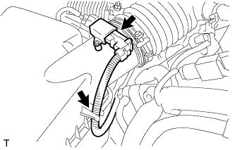
Disconnect the clamp from the air cleaner.
Disconnect the VSV hose.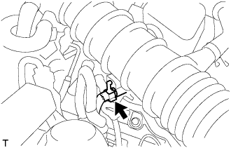
Disconnect the 4 clamps.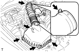
Remove the hose clamp and air cleaner cap with air cleaner hose.
| 20. REMOVE AIR CLEANER CASE SUB-ASSEMBLY |
Remove the 2 bolts, clamp and air cleaner case.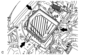
| 21. DISCONNECT UNION TO CHECK VALVE HOSE |
Remove the clamp and disconnect the union to check valve hose.
| 22. DISCONNECT NO.2 FUEL VAPOR FEED HOSE |
Remove the clamp and disconnect the No. 2 fuel vapor feed hose.
| 23. DISCONNECT INLET RADIATOR HOSE |
Remove the clamp and disconnect the inlet radiator hose.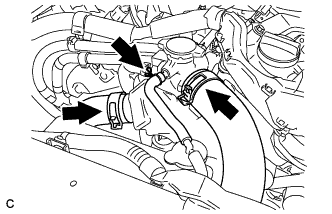
| 24. DISCONNECT OUTLET RADIATOR HOSE |
Remove the clamp and disconnect the outlet radiator hose.
| 25. DISCONNECT RADIATOR RESERVOIR TANK HOSE |
Remove the clamp and disconnect the radiator reservoir tank hose.
| 26. DISCONNECT INLET HEATER WATER HOSE |
Disconnect the inlet heater water hose.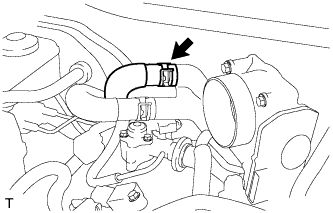
| 27. DISCONNECT OUTLET HEATER WATER HOSE |
Disconnect the outlet heater water hose.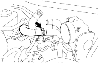
| 28. REMOVE NO. 1 COOLER REFRIGERANT SUCTION HOSE |
Remove the bolt and disconnect the No. 1 cooler refrigerant suction hose from the compressor.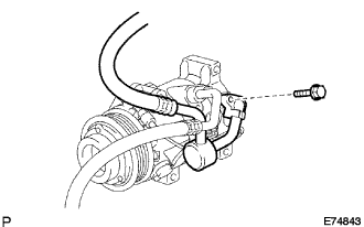
Remove the O-ring from the cooler refrigerant suction hose.
- NOTICE:
- Seal the openings of the disconnected parts using vinyl tape to prevent moisture and foreign matter from entering.
| 29. REMOVE DISCHARGE HOSE SUB-ASSEMBLY |
Remove the bolt and disconnect the discharge hose from the compressor.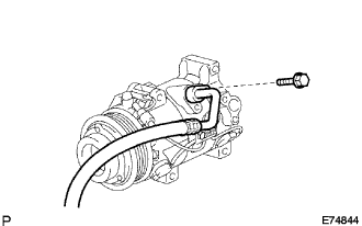
Remove the O-ring from the discharge hose sub-assembly.
- NOTICE:
- Seal the openings of the disconnected parts using vinyl tape to prevent moisture and foreign matter from entering.
| 30. REMOVE ECM COVER |
Remove the 3 bolts and ECM cover.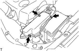
- NOTICE:
- Remove all water from on and around the ECM cover.
- Perform the inspection indoors to avoid rain.
- Be sure to prevent water intrusion to the ECM (connectors and screw parts).
- Remove all water from on and around the ECM cover.
| 31. DISCONNECT ENGINE WIRE |
Disconnect the 6 ECM connectors.
Using a screwdriver, disconnect the connector holder.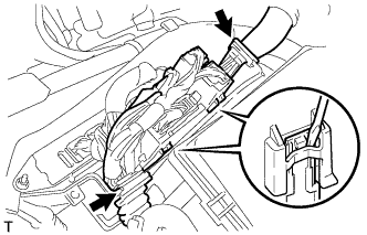
Remove the engine room No. 1 relay block cover.
Remove the nut and disconnect the wire from the engine room No. 1 junction block.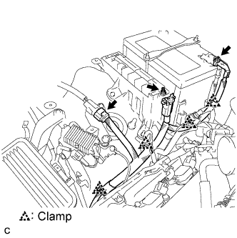
Remove the nut and disconnect the battery positive (+) cable.
Disconnect the connector and remove the 4 clamps from body.
Remove the bolt, clamp and engine wire No. 3.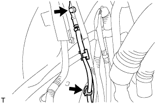
Remove the bolt and disconnect the ground cable.
| 32. DISCONNECT FUEL MAIN TUBE |
| 33. DISCONNECT NO. 3 FUEL HOSE |
Remove the clamp and disconnect the No. 3 fuel hose.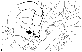
| 34. REMOVE FRONT LOWER SUSPENSION MEMBER PROTECTOR |
Remove the 4 bolts and suspension member protector.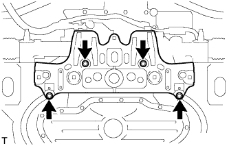
| 35. DISCONNECT STEERING SLIDING WITH SHAFT YOKE SUB-ASSEMBLY |
Fix the steering wheel with the seat belt in order to prevent rotation.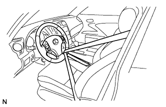
- HINT:
- This operation is useful to prevent damage to the spiral cable.
Loosen bolt (A) and remove bolt (B), then slide the steering sliding yoke sub-assembly.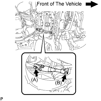
- NOTICE:
- Do not remove bolt (A).
- Do not separate the steering sliding yoke sub-assembly from the power steering gear assembly.
- Do not remove bolt (A).
Put matchmarks on the steering sliding yoke sub-assembly and the power steering gear assembly.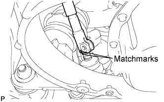
Separate the steering sliding yoke sub-assembly from the power steering gear assembly.
| 36. DISCONNECT HEIGHT CONTROL SENSOR LINK |
Remove the nut and disconnect the height control sensor link.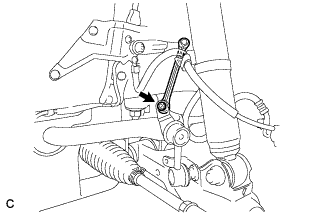
| 37. REMOVE FRONT SHOCK ABSORBER ASSEMBLY LH |
Loosen the bolt while holding the nut. Separate the lower part of the front shock absorber from the front suspension lower arm.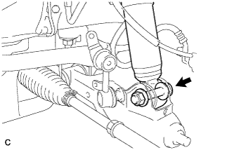
| 38. REMOVE FRONT SHOCK ABSORBER ASSEMBLY RH |
- HINT:
- Remove the RH side following the same procedures as for the LH side.
| 39. REMOVE FRONT LOWER BALL JOINT ASSEMBLY LH |
Remove the 2 bolts from the front lower ball joint.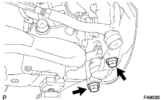
| 40. REMOVE FRONT LOWER BALL JOINT ASSEMBLY RH |
- HINT:
- Remove the RH side following the same procedures as for the LH side.
| 41. REMOVE EXHAUST PIPE NO. 1 SUPPORT BRACKET SUB-ASSEMBLY (for Automatic Transmission) |
Remove the 2 bolts and exhaust pipe No. 1 support bracket sub-assembly.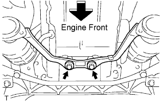
| 42. DISCONNECT POWER STEERING LINK WIRE HARNESS |
Remove the bolt (A) to disconnect the earth wire from the bracket.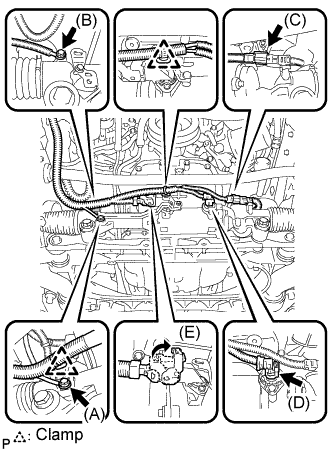
Remove the 2 clamps to disconnect the wire harness from the bracket.
Disconnect the 2 connectors (C) and (D) from the power steering link assembly.
Release the lock of connector (E) and disconnect the connector from the power steering link assembly.
Remove the bolt (B) and the power steering earth wire from the power steering link assembly.
| 43. DISCONNECT FLOOR SHIFT GEAR SHIFTING ROD SUB-ASSEMBLY |
Set the shift lever to the neutral position.
Remove the nut, and separate the floor shift gear shifting rod sub-assembly.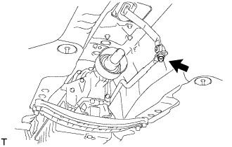
| 44. REMOVE ENGINE AND TRANSMISSION ASSEMBLY |
Set the engine lifter.
Remove the 4 bolts, then separate the engine rear mounting member.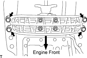
Remove the 12 bolts shown in the illustration.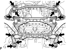
Operate the engine lifter, then slowly remove the engine from the vehicle.
- NOTICE:
- Make sure that the engine is clear of all wiring and hoses.
| 45. INSTALL ENGINE HANGERS |
Install the No. 1 and No. 2 or No. 3 engine hangers with the 4 bolts as shown in the illustration.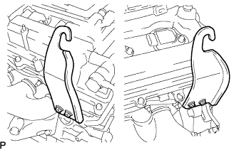
- Torque:
- 33 N*m{ 336 kgf*cm , 24 ft.*lbf }
Part No.: No. 1 engine hanger
12281 - 31070
No. 2 engine hanger
12282 - 31050
Bolts
91671 - 10825
Attach an engine sling device and hang the engine with a chain block.
| 46. REMOVE STARTER ASSEMBLY |
Disconnect the terminal 50 connector from the starter assembly.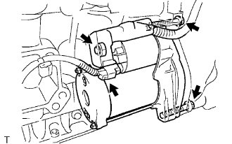
Detach the terminal cap.
Remove the nut and disconnect the wire harness from terminal 30.
Remove the 2 bolts and starter.
| 47. REMOVE MANUAL TRANSMISSION ASSEMBLY (for Manual Transmission) |
| 48. REMOVE AUTOMATIC TRANSMISSION ASSEMBLY (for Automatic Transmission) |
| 49. REMOVE OIL DIPSTICK GUIDE SUB-ASSEMBLY |
Remove the oil level gauge.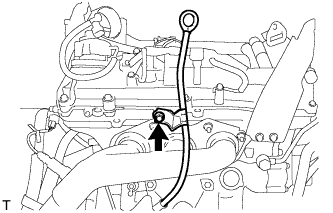
Remove the bolt, then remove the No. 2 oil dipstick guide.
Remove the O-ring from the No. 2 oil dipstick guide.
Remove the bolt and clamp, then remove the No. 1 oil dipstick guide.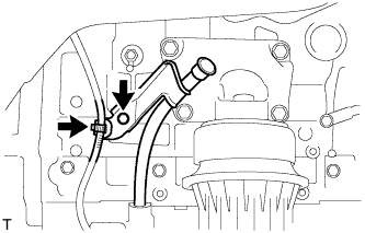
Remove the O-ring from the No. 1 oil dipstick guide.
| 50. REMOVE EXHAUST MANIFOLD SUB-ASSEMBLY LH |
Disconnect the heated oxygen sensor connector.
Remove the 6 nuts, exhaust manifold and gasket.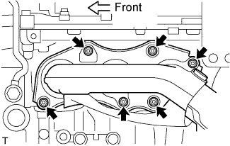
| 51. REMOVE EXHAUST MANIFOLD SUB-ASSEMBLY RH |
Disconnect the heated oxygen sensor connector.
Remove the 6 nuts, exhaust manifold and gasket.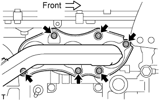
| 52. REMOVE FLYWHEEL SUB-ASSEMBLY (for Manual Transmission) |
Using SST, hold the crankshaft.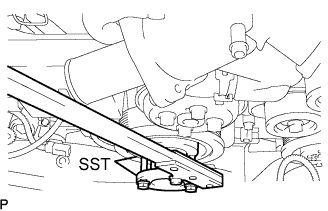
- SST
- 09213-70011
(09213-70020)
09330-00021
Remove the 8 bolts and the flywheel.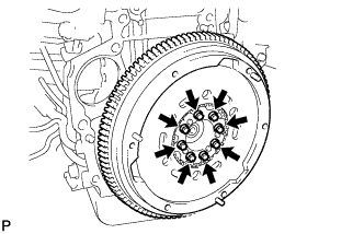
| 53. REMOVE DRIVE PLATE AND RING GEAR SUB-ASSEMBLY (for Automatic Transmission) |
Using SST, hold the crankshaft.
- SST
- 09213-70011
(09213-70020)
09330-00021
Remove the 8 bolts, front spacer, drive plate and rear spacer.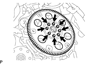
| 54. REMOVE FRONT SUSPENSION CROSSMEMBER SUB-ASSEMBLY |
Remove the 2 bolts, then separate the front suspension crossmember sub-assembly from the engine.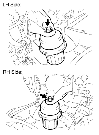
| 55. FIX ENGINE ON ENGINE STAND |
Fix the engine onto a engine stand with the bolts.
| 56. REMOVE V-RIBBED BELT |
While releasing the belt tension by turning the belt tensioner counterclockwise, and remove the V-ribbed belt from the belt tensioner.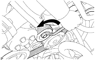
While turning the belt tensioner counterclockwise, align with its holes, and then insert the 5 mm bi-hexagon wrench into the holes to fix the belt tensioner.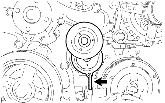
| 57. REMOVE NO. 2 ENGINE COVER |
Remove the 3 clips and clamp, then remove the No. 2 engine cover.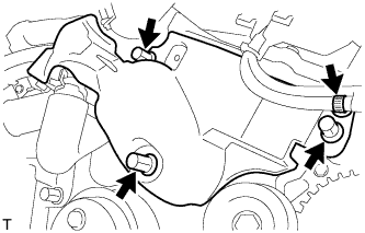
| 58. REMOVE NO. 1 ENGINE COVER |
Remove the 3 clips, then remove the No. 1 engine cover.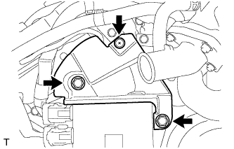
| 59. REMOVE NO. 2 IDLER PULLEY SUB-ASSEMBLY |
Remove the bolt, plate and idler pulley.
| 60. REMOVE GENERATOR ASSEMBLY |
Remove the terminal cap.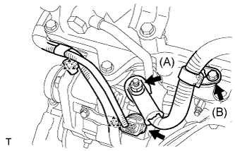
Remove the nut (A) and disconnect the wire harness from terminal B.
Remove the bolt (B) and clamp bracket.
Disconnect the generator connector, and detach the 2 clamps.
Remove the nut, and disconnect the generator bracket.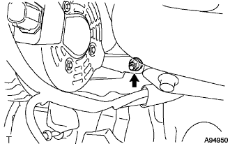
Remove the 2 bolts and generator.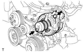
Remove the 2 bolts and 2 generator brackets.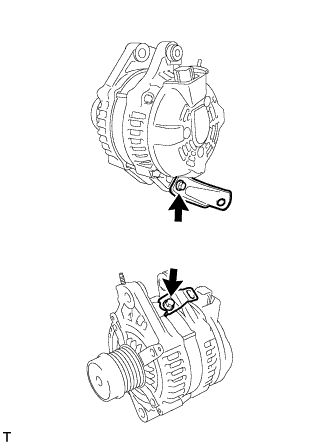
| 61. REMOVE COOLER COMPRESSOR ASSEMBLY |
Disconnect the magnetic clutch connector.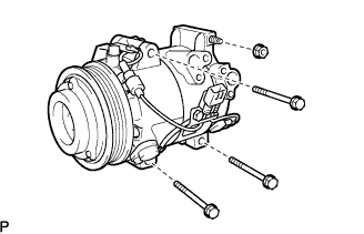
Remove the 3 bolts and nut.
Remove the compressor and magnetic clutch.
| 62. REMOVE ENGINE MOUNTING BRACKET LH |
Disconnect the 2 clamps.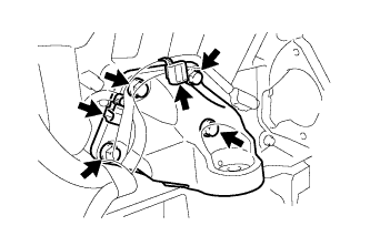
Remove the 4 bolts and mounting bracket.
| 63. REMOVE ENGINE MOUNTING BRACKET RH |
Remove the 4 bolts and mounting bracket.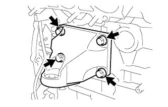
| 64. REMOVE V-RIBBED BELT TENSIONER ASSEMBLY |
Remove the 5 bolts, then remove the V-ribbed belt tensioner assembly.)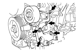
| 65. REMOVE WATER PUMP PULLEY |
Using SST, hold the water pump pulley.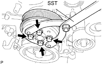
- SST
- 09960-10010
(09962-01000, 09963-00700)
Remove the 4 bolts and water pump pulley.
| 66. REMOVE ENGINE WIRE |
Remove the engine wire from the engine.
| 67. REMOVE INJECTOR DRIVER |
Remove the bolt, 2 nuts and injector driver.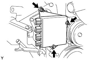
| 68. REMOVE INTAKE AIR SURGE TANK ASSEMBLY |
| 69. REMOVE NO. 2 SURGE TANK STAY |
Remove the bolt and No. 2 surge tank stay.
| 70. REMOVE WATER HOSE JOINT |
Remove the bolt, and disconnect 2 hoses and water hose joint.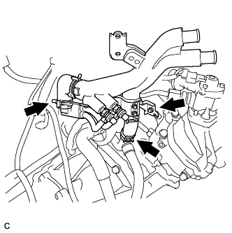
| 71. REMOVE CRANKSHAFT PULLEY |
Using SST, loosen the pulley bolt.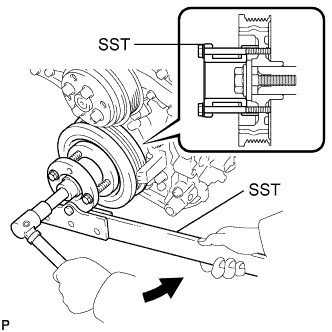
- SST
- 09950-50013
(09951-05010, 09952-05010, 09953-05020, 09954-05021)
Tighten the pulley bolt to 2 or 3 threads of the crankshaft.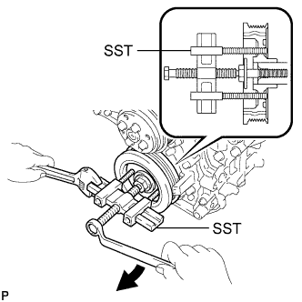
Using SST, remove the pulley bolt and pulley.
- SST
- 09213-70011
(09213-70020)
09330-00021
- HINT:
- Apply grease to the threads and tip of the SST (center bolt) prior to use.
Remove the pulley set key of the key groove.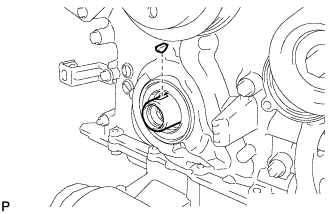
| 72. REMOVE WATER INLET |
Disconnect the 5 hoses.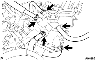
Remove the 4 bolts, nut and water inlet.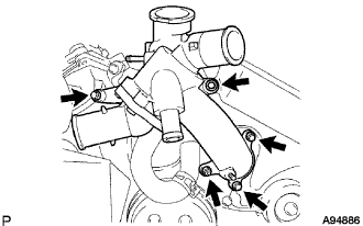
Remove the water inlet housing gasket and water outlet pipe O-ring.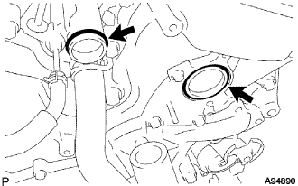
| 73. REMOVE NO. 2 OIL PAN SUB-ASSEMBLY |
Remove the 15 bolts and 2 nuts.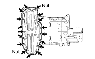
Insert the blade of SST between the oil pans. Cut through the applied sealer and remove the No. 2 oil pan sub-assembly.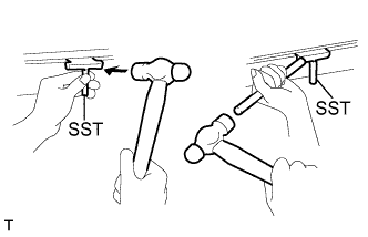
- SST
- 09032-00100
- NOTICE:
- Be careful not to damage the contact surfaces of the oil pans.
| 74. REMOVE OIL PAN SUB-ASSEMBLY |
Remove the 16 bolts and 2 nuts.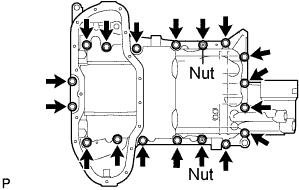
- HINT:
- Be sure to clean the bolts and stud bolts and check the threads for cracks or other damage.
Remove the oil pan by prying between the oil pan and cylinder block with a screwdriver.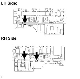
- NOTICE:
- Be careful not to damage the contact surfaces of the cylinder block and oil pan.
- HINT:
- Tape the screwdriver tip before use.
Remove the 2 O-rings.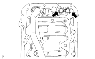
| 75. REMOVE OIL STRAINER SUB-ASSEMBLY |
Remove the 3 nuts, oil strainer and gasket.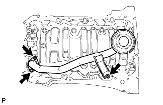
Remove the 8 bolts and baffle plate.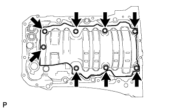
| 76. REMOVE FUEL PRESSURE PULSATION DAMPER ASSEMBLY |
Using SST, remove the fuel pressure pulsation damper from the fuel pump.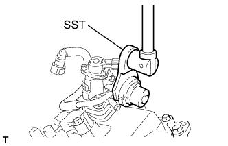
| 77. REMOVE NO. 1 FUEL PIPE |
Disconnect the No. 3 fuel hose from the No. 1 fuel pipe.
Disconnect the 2 fuel hoses.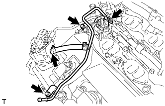
Remove the 2 bolts and No. 1 fuel pipe.
| 78. DISCONNECT NO. 2 FUEL PIPE |
Disconnect the fuel high pressure side fuel pump connector.
Fix the union bolt on the fuel pump side in place with a 21 mm wrench. Using a 19 mm union nut wrench, loosen the union and remove the fuel pipe.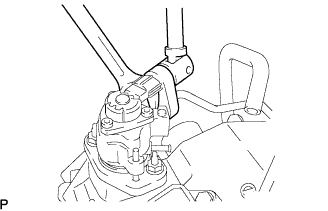
- NOTICE:
- There must be absolutely no free play in the union on the fuel pump side.
- If the union on the fuel pump side has free play, replace the fuel pump.
- There must be absolutely no free play in the union on the fuel pump side.
Remove the 2 bolts on the delivery pipe side.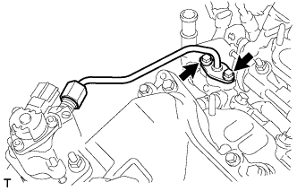
- NOTICE:
- Do not remove the fuel pipe from the delivery pipe. Only remove the 2 bolts.
- If the No. 2 fuel pipe is accidentally removed, replace its O-ring, No. 1 backup ring and No. 2 backup ring.
- Do not remove the fuel pipe from the delivery pipe. Only remove the 2 bolts.
| 79. REMOVE FUEL PUMP ASSEMBLY |
Disconnect the fuel hose.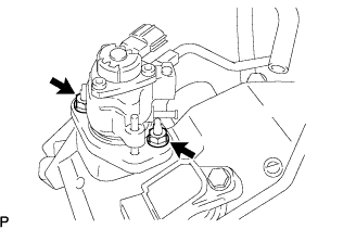
Remove the 2 nuts, fuel pump and fuel pump insulator.
| 80. REMOVE NO. 2 FUEL PIPE |
Remove the fuel pipe from the fuel delivery pipe.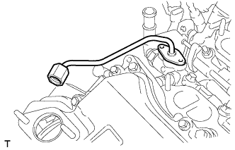
- NOTICE:
- Pull and remove the fuel pipe in a straight line to avoid damage to the seal surface of the delivery pipe's O-ring.
Remove the O-ring, backup rings and E-ring from the No. 2 fuel pipe.
| 81. REMOVE IGNITION COIL ASSEMBLY |
Remove the 6 bolts and 6 ignition coils.
| 82. REMOVE NO. 1 OIL PIPE |
Remove the oil check valve bolt, oil pipe union and oil pipe.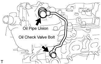
Remove the oil control valve filter LH and gaskets.
| 83. REMOVE NO. 2 OIL PIPE |
Remove the oil check valve bolt, oil pipe union and oil pipe.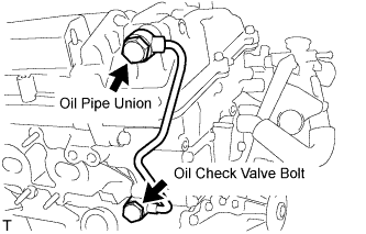
Remove the oil control valve filter RH and gaskets.
| 84. REMOVE CYLINDER HEAD COVER SUB-ASSEMBLY (for Bank 2) |
Remove the 14 bolts, head cover and gasket.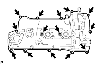
Remove the 3 gaskets.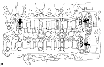
| 85. REMOVE CYLINDER HEAD COVER SUB-ASSEMBLY (for Bank 1) |
Remove the 12 bolts, head cover and gasket.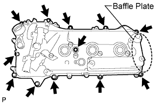
- NOTICE:
- The baffle plate is located on the back of the portion shown in the illustration. Do not damage the baffle plate when removing the head cover.
Remove the 3 gaskets.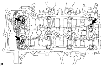
| 86. REMOVE TIMING CHAIN COVER SUB-ASSEMBLY |
Remove the bolt and wiring harness clamp bracket.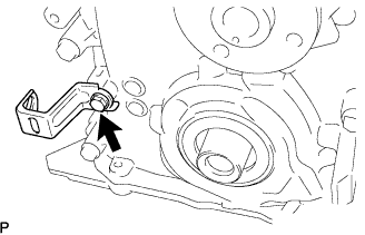
Remove the 25 bolts and 2 nuts as shown in the illustration.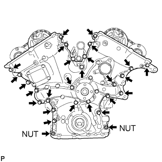
Remove the timing chain cover by prying between the timing chain cover and cylinder head or cylinder block with a screwdriver.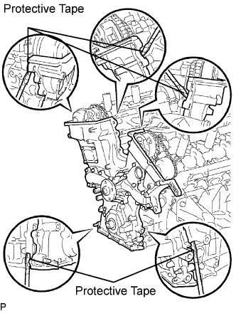
- NOTICE:
- Be careful not to damage the contact surfaces of the cylinder head, cylinder block and chain cover.
- HINT:
- Tape the screwdriver tip before use.
Remove the gasket.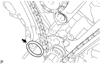
| 87. REMOVE TIMING CHAIN CASE OIL SEAL |
Using a screwdriver, pry out the oil seal.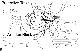
- HINT:
- Tape the screwdriver tip before use.