INSTALLATION
Removal / installation
| 1. INSTALL ENGINE COOLANT TEMPERATURE SENSOR |

Using a 19 mm deep socket wrench, install the temperature sensor.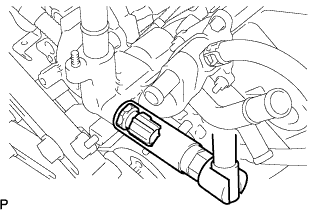

- Torque:
- 20 N*m{ 204 kgf*cm , 15 ft.*lbf }
| 2. INSTALL OIL PRESSURE SWITCH ASSEMBLY |
Apply adhesive to 2 or 3 threads of the oil pressure switch.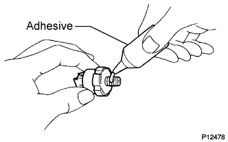
- Adhesive:
- Part No.08833-00080 THREE BOND 1344, LOCTITE 242 or equivalent.
Using a 24 mm deep socket wrench, install the oil pressure switch.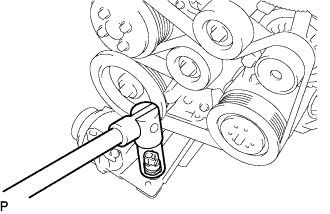
- Torque:
- 15 N*m{ 153 kgf*cm , 11 ft.*lbf }
- NOTICE:
- Do not start the engine within 1 hour after installation for prevent oil leaks.
| 3. INSTALL ENGINE OIL LEVEL SENSOR |
Install the engine oil level sensor and a new gasket with the 4 bolts.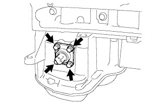
- Torque:
- 7.0 N*m{ 71 kgf*cm , 62 in.*lbf }
| 4. INSTALL IGNITION COIL ASSEMBLY |
Install the 6 ignition coils with the 6 bolts.
- Torque:
- 10 N*m{ 102 kgf*cm , 7 ft.*lbf }
| 5. INSTALL V-BANK COVER BRACKET SUB-ASSEMBLY |
Install the V-bank cover bracket with the bolt.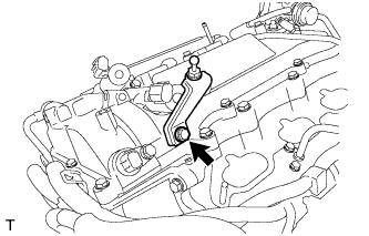
- Torque:
- 10 N*m{ 102 kgf*cm , 7 ft.*lbf }
| 6. INSTALL RADIO SETTING CONDENSER |
Install the 2 bolts and 2 radio setting condensers.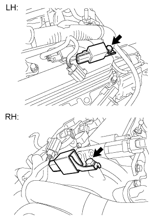
- Torque:
- 10 N*m{ 102 kgf*cm , 7 ft.*lbf }
| 7. INSTALL KNOCK SENSOR |
Install the 2 knock sensors so that they are horizontal as shown in the illustration. Then install the 2 bolts.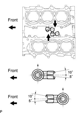
- Torque:
- 20 N*m{ 204 kgf*cm , 15 ft.*lbf }
- HINT:
- It is acceptable for the knock sensor to be tilted +10° to -5°.
Connect the 2 knock sensor connectors.
| 8. INSTALL FUEL INJECTOR ASSEMBLY |
- HINT:
- Click here.
| 9. INSTALL FUEL PUMP |
- HINT:
- Click here.
| 10. INSTALL INTAKE MANIFOLD |
Install a new gasket and the intake manifold with the 4 bolts and 4 nuts.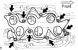
- Torque:
- 21 N*m{ 214 kgf*cm , 15 ft.*lbf }
Connect the SCV position sensor connector.
Connect the DC motor connector for the SCV.
| 11. INSTALL WATER HOSE JOINT |
Connect the 2 hoses, and install the bolt and water hose joint.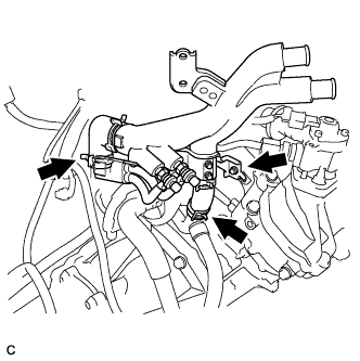
- Torque:
- 10 N*m{ 102 kgf*cm , 7 ft.*lbf }
| 12. INSTALL NO. 2 SURGE TANK STAY |
Install the bolt and No. 2 surge tank stay.
- Torque:
- 21 N*m{ 214 kgf*cm , 15 ft.*lbf }
| 13. INSTALL INTAKE AIR SURGE TANK ASSEMBLY |
- HINT:
- Click here.
| 14. INSTALL INJECTOR DRIVER |
Install the injector driver with the bolt and 2 nuts.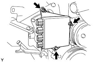
- Torque:
- 10 N*m{ 102 kgf*cm , 7 ft.*lbf }
| 15. INSTALL ENGINE WIRE |
Install the engine wire to the engine assembly.
| 16. INSTALL WATER PUMP PULLEY |
Temporarily install the pulley with the 4 bolts.
Using SST, hold the pulley and tighten the 4 bolts.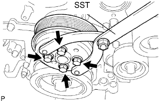
- SST
- 09960-10010
(09962-01000, 09963-00700)
- Torque:
- 21 N*m{ 214 kgf*cm , 15 ft.*lbf }
| 17. INSTALL V-RIBBED BELT TENSIONER ASSEMBLY |
Temporarily install the V-ribbed belt tensioner with the 5 bolts.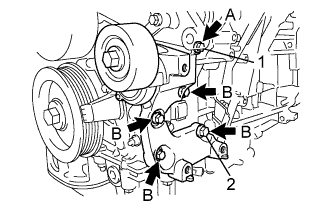
- Each bolt length is as follows:
Mark
Specified Length
A
70 mm (2.76 in.)
B
35 mm (1.38 in.)
Install the V-ribbed belt tensioner by tightening the bolt 1 and bolt 2 in the order shown in the illustration.
- Torque:
- 43 N*m{ 439 kgf*cm , 32 ft.*lbf }
Tighten the other bolts.
- Torque:
- 43 N*m{ 439 kgf*cm , 32 ft.*lbf }
| 18. INSTALL ENGINE MOUNTING BRACKET LH |
Install the mounting bracket with the 4 bolts.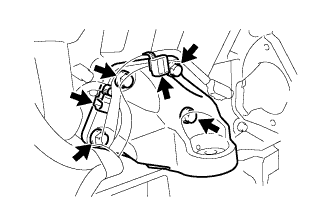
- Torque:
- 43 N*m{ 439 kgf*cm , 32 ft.*lbf }
Connect the 2 clamps.
| 19. INSTALL ENGINE MOUNTING BRACKET RH |
Install the mounting bracket with the 4 bolts.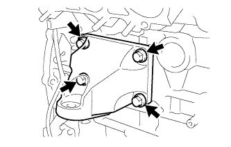
- Torque:
- 43 N*m{ 439 kgf*cm , 32 ft.*lbf }
| 20. INSTALL COOLER COMPRESSOR ASSEMBLY |
Temporarily install the compressor and magnetic clutch onto the stud bolt.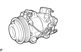
Install the compressor and magnetic clutch with the 3 bolts and nut.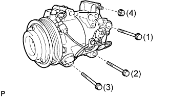
- Torque:
- 25 N*m{ 255 kgf*cm , 18 ft.*lbf }
- NOTICE:
- Tighten the bolts in the order shown in the illustration to install the compressor and magnetic clutch.
| 21. INSTALL GENERATOR ASSEMBLY |
Install the 2 generator brackets with the 2 bolts.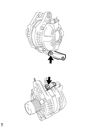
- Torque:
- 20 N*m{ 204 kgf*cm , 15 ft.*lbf }
Install the generator assembly with the 2 bolts.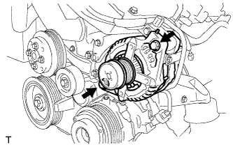
- Torque:
- 43 N*m{ 438 kgf*cm , 32 ft.*lbf }
Install the bracket with the nut.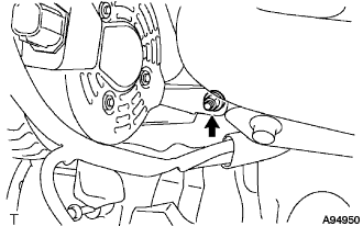
- Torque:
- 20 N*m{ 204 kgf*cm , 15 ft.*lbf }
Install the generator wire to terminal B with the nut (A).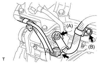
- Torque:
- 9.8 N*m{ 100 kgf*cm , 87 in.*lbf }
Install the terminal cap.
Install the clamp bracket with the bolt (B).
- Torque:
- 10 N*m{ 102 kgf*cm , 7 ft.*lbf }
Attach the 2 clamps, and connect the generator connector to the generator.
| 22. INSTALL NO. 2 IDLER PULLEY SUB-ASSEMBLY |
Install the plate and idler pulley with the bolt.
- Torque:
- 43 N*m{ 439 kgf*cm , 32 ft.*lbf }
| 23. INSTALL NO. 1 ENGINE COVER |
Install the No. 1 engine cover with the 3 clips.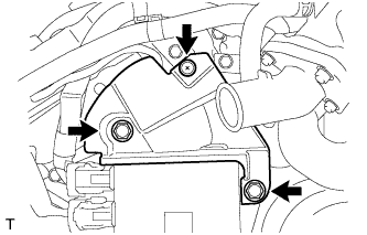
| 24. INSTALL NO. 2 ENGINE COVER |
Install the No. 2 engine cover with the 3 clips.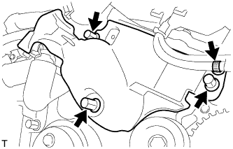
Connect the clamp.
| 25. INSTALL V-RIBBED BELT |
Install the V-ribbed belt.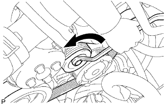
While turning the belt tensioner counterclockwise, remove the bar.
- NOTICE:
- Put the backside of the V-ribbed belt on the tensioner pulley and idler pulley.
- Check that the V-ribbed belt is properly set to each pulley.
- Put the backside of the V-ribbed belt on the tensioner pulley and idler pulley.
If it is difficult to install the V-ribbed belt, perform the following procedure.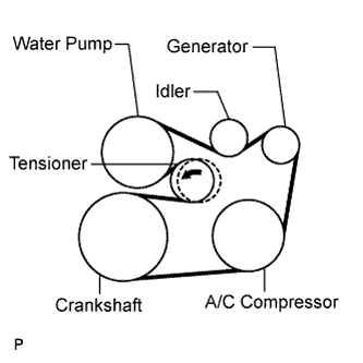
Put the V-ribbed belt on every part except the tensioner pulley as shown in the illustration.
While releasing the belt tension by turning the belt tensioner counterclockwise, put the V-ribbed belt on the tensioner pulley.
- NOTICE:
- Put the backside of the V-ribbed belt on the tensioner pulley and idler pulley.
- Check that the V-ribbed belt is properly set to each pulley.
- Put the backside of the V-ribbed belt on the tensioner pulley and idler pulley.
| 26. INSTALL ENGINE HANGERS |
- Torque:
- 33 N*m{ 336 kgf*cm , 24 ft.*lbf }
| 27. INSTALL FLYWHEEL SUB-ASSEMBLY (for Manual Transmission) |
Hold the crankshaft with SST.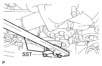
- SST
- 09213-70011
(09213-70020)
09330-00021
Using several steps, install and tighten 8 new bolts uniformly in the sequence shown in the illustration.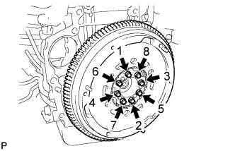
- Torque:
- 73 N*m{ 741 kgf*cm , 54 ft.*lbf }
- NOTICE:
- Do not reuse the flywheel installation bolts. Be sure to check the tightening torque within 5 minutes after tightening.
- Do not impact or damage the flywheel installation bolts. Be sure to handle them carefully.
- Make sure that the seating surface of the flywheel installation bolts and installation surfaces of the crankshaft and flywheel are free of oil or foreign matter.
- Do not reuse the flywheel installation bolts. Be sure to check the tightening torque within 5 minutes after tightening.
| 28. INSTALL DRIVE PLATE AND RING GEAR SUB-ASSEMBLY (for Automatic Transmission) |
Using SST, hold the crankshaft.
- SST
- 09213-70011
(09213-70020)
09330-00021
Apply adhesive to 2 or 3 threads of the mounting bolts ends.
- Adhesive:
- Part No. 08833-00070, THREE BOND 1324 or equivalent
Install the front spacer, drive plate and rear spacer on the crankshaft.
Install and tighten the 8 mounting bolts uniformly in several steps.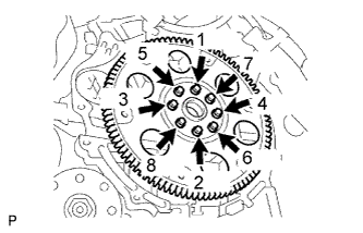
- Torque:
- 83 N*m{ 846 kgf*cm , 61 ft.*lbf }
- NOTICE:
- Do not start the engine for at least 1 hour after installing.
| 29. INSTALL FRONT SUSPENSION CROSSMEMBER SUB-ASSEMBLY |
Install the front suspension crossmember sub-assembly with the 2 bolts.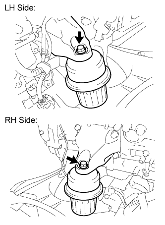
- Torque:
- 35 N*m{ 357 kgf*cm , 26 ft.*lbf }
| 30. INSTALL MANUAL TRANSMISSION ASSEMBLY (for Manual Transmission) |
- HINT:
- Click here.
| 31. INSTALL AUTOMATIC TRANSMISSION ASSEMBLY (for Automatic Transmission) |
- HINT:
- Click here.
| 32. INSTALL STARTER ASSEMBLY |
Install the starter with the 2 bolts.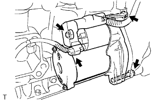
- Torque:
- 58 N*m{ 591 kgf*cm , 43 ft.*lbf }
Connect the wire harness to terminal 30 and install the nut, and then attach the terminal cap.
- Torque:
- 9.8 N*m{ 100 kgf*cm , 87 in.*lbf }
Connect the terminal 50 connector to the starter assembly.
| 33. INSTALL EXHAUST MANIFOLD SUB-ASSEMBLY LH |
Install a new gasket as shown in the illustration.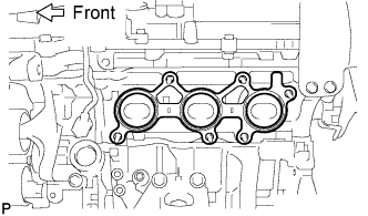
Install the exhaust manifold with 6 new nuts.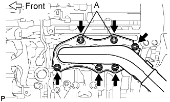
- Torque:
- 21 N*m{ 214 kgf*cm , 15 ft.*lbf }
- NOTICE:
- Do not damage the stud bolt when installing the exhaust manifold.
- Be sure to tighten either of nuts A first as shown in the illustration.
- Do not damage the stud bolt when installing the exhaust manifold.
| 34. INSTALL EXHAUST MANIFOLD SUB-ASSEMBLY RH |
Install a new gasket as shown in the illustration.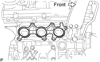
Install the exhaust manifold with 6 new nuts.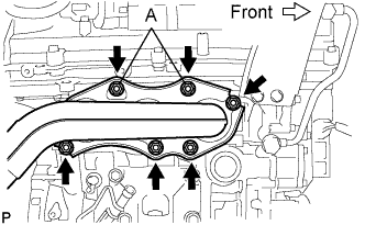
- Torque:
- 21 N*m{ 214 kgf*cm , 15 ft.*lbf }
- NOTICE:
- Do not damage the stud bolt when installing the exhaust manifold.
- Be sure to tighten either of nuts A first as shown in the illustration.
- Do not damage the stud bolt when installing the exhaust manifold.
| 35. INSTALL OIL DIPSTICK GUIDE SUB-ASSEMBLY |
Install a new O-ring to the oil dipstick guide.
Apply a light coat of engine oil to the O-ring.
Push in the oil dipstick guide end into the guide hole.
Install the No. 1 oil dipstick guide with the bolt.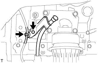
- Torque:
- 10 N*m{ 102 kgf*cm , 7 ft.*lbf }
Connect the clamp.
Install the No. 2 oil dipstick guide with the bolt.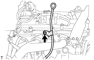
- Torque:
- 21 N*m{ 214 kgf*cm , 15 ft.*lbf }
Install the oil dipstick.
| 36. INSTALL ENGINE AND TRANSMISSION ASSEMBLY |
Set the engine lifter.
Operate the engine lifter, then install the engine to the vehicle.
Install the engine and transmission assembly with crossmember with the 12 bolts.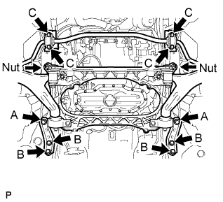
- Torque:
- 167 N*m{ 1,700 kgf*cm , 123 ft.*lbf } for Nut
- 204 N*m{ 2,080 kgf*cm , 150 ft.*lbf } for bolt A
- 50 N*m{ 510 kgf*cm , 37 ft.*lbf } for bolt B
- 49 N*m{ 500 kgf*cm , 36 ft.*lbf } for bolt C
Install the engine rear mounting member with the 4 bolts.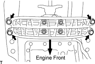
- Torque:
- 26 N*m{ 265 kgf*cm , 19 ft.*lbf }
| 37. CONNECT FLOOR SHIFT GEAR SHIFTING ROD SUB-ASSEMBLY |
Temporarily tighten the floor shift gear shifting rod sub-assembly with the nut.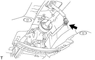
| 38. CONNECT POWER STEERING LINK WIRE HARNESS |
Install the power steering earth wire to the power steering link assembly with bolt (B).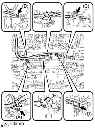
- Torque:
- 13 N*m{ 130 kgf*cm , 10 ft.*lbf }
Connect the wire harness connector (E) to the power steering link assembly and securely lock the connector.
Connect the 2 wire harness connectors (C) and (D) to the power steering link assembly.
Install the 2 wire harness clamps to the power steering link assembly.
Connect the earth wire to the bracket with bolt (A).
- Torque:
- 5.0 N*m{ 51 kgf*cm , 44 in.*lbf }
| 39. INSTALL EXHAUST PIPE NO. 1 SUPPORT BRACKET SUB-ASSEMBLY (for Automatic Transmission) |
Install the exhaust pipe No. 1 support bracket sub-assembly with the 2 bolts.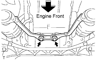
- Torque:
- 43 N*m{ 438 kgf*cm , 32 ft.*lbf }
| 40. INSTALL FRONT LOWER BALL JOINT ASSEMBLY LH |
Install the front lower ball joint with the 2 bolts.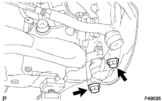
- Torque:
- 120 N*m{ 1,224 kgf*cm , 89 ft.*lbf }
| 41. INSTALL FRONT LOWER BALL JOINT ASSEMBLY RH |
- HINT:
- Install the RH side following the same procedures as for the LH side.
| 42. INSTALL FRONT SHOCK ABSORBER ASSEMBLY LH |
Install the bolt on the lower side of the front shock absorber while holding the nut.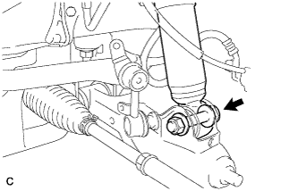
- Torque:
- 157 N*m{ 1,600 kgf*cm , 116 ft.*lbf }
| 43. INSTALL FRONT SHOCK ABSORBER ASSEMBLY RH |
- HINT:
- Install the RH side following the same procedures as for the LH side.
| 44. CONNECT HEIGHT CONTROL SENSOR LINK |
Connect the height control sensor link and install it with the nut.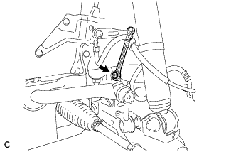
- Torque:
- 5.4 N*m{ 55 kgf*cm , 48 in.*lbf }
| 45. CONNECT STEERING SLIDING WITH SHAFT YOKE SUB-ASSEMBLY |
Align the matchmarks on the steering sliding yoke sub-assembly and the power steering gear assembly.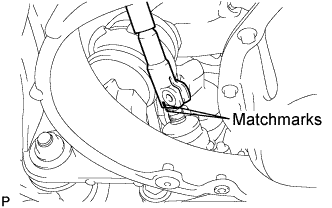
Install bolt (A) and tighten the 2 bolts.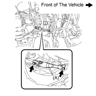
- Torque:
- 35 N*m{ 360 kgf*cm , 26 ft.*lbf }
| 46. INSTALL FRONT LOWER SUSPENSION MEMBER PROTECTOR |
Install the protector with the 4 bolts.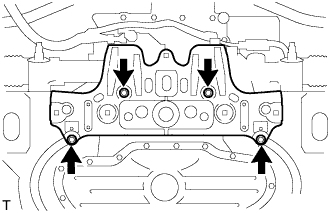
- Torque:
- 8.0 N*m{ 82 kgf*cm , 71 in.*lbf }
| 47. CONNECT NO. 3 FUEL HOSE |
Connect the No. 3 fuel hose and clamp.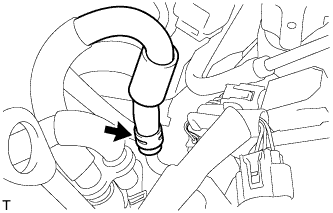
| 48. CONNECT FUEL MAIN TUBE |
- HINT:
- Click here.
| 49. CONNECT ENGINE WIRE |
Install the bolt, clamp and engine wire No. 3.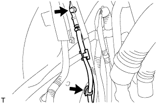
- Torque:
- 8.5 N*m{ 87 kgf*cm , 75 in.*lbf }
Connect the ground cable and install it with the bolt.
- Torque:
- 13 N*m{ 133 kgf*cm , 10 ft.*lbf }
Connect the connector and install the 4 clamps to the body.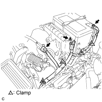
Connect the wire to the engine room No. 1 junction block. Then, install it with the nut.
- Torque:
- 12 N*m{ 124 kgf*cm , 9 ft.*lbf }
Install the engine room No. 1 relay block cover.
Connect the battery positive (+) cable and install it with the nut.
- Torque:
- 13 N*m{ 133 kgf*cm , 10 ft.*lbf }
Connect the ECM connectors.
Connect the connector holder.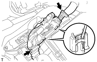
| 50. INSTALL ECM COVER |
Install the ECM cover with the 3 bolts.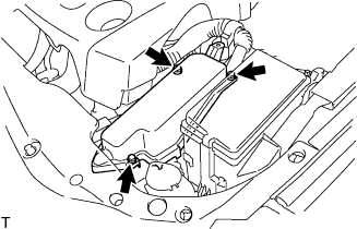
- Torque:
- 5.5 N*m{ 56 kgf*cm , 49 in.*lbf }
- NOTICE:
- Make sure that the wire harness does not get caught between the parts.
| 51. CONNECT DISCHARGE HOSE SUB-ASSEMBLY |
Remove the attached vinyl tape from the hose.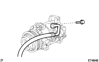
Apply sufficient compressor oil (ND-OIL 8) to a new O-ring and the fitting surface of the compressor and magnetic clutch.
- Compressor oil:
- ND-OIL 8 or equivalent
Install the O-ring onto the discharge hose sub-assembly.
Install the discharge hose sub-assembly onto the compressor and magnetic clutch with the bolt.
- Torque:
- 9.8 N*m{ 100 kgf*cm , 87 in.*lbf }
| 52. CONNECT NO. 1 COOLER REFRIGERANT SUCTION HOSE |
Remove the attached vinyl tape from the hose.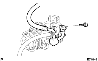
Apply sufficient compressor oil to a new O-ring and the fitting surface of the compressor and magnetic clutch.
- Compressor oil:
- ND-OIL 8 or equivalent
Install the O-ring onto the No.1 cooler refrigerant suction hose.
Install the No. 1 cooler refrigerant suction hose onto the compressor and magnetic clutch with the bolt.
- Torque:
- 9.8 N*m{ 100 kgf*cm , 87 in.*lbf }
| 53. CONNECT INLET HEATER WATER HOSE |
Connect the inlet heater water hose.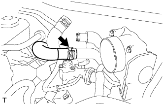
| 54. CONNECT OUTLET HEATER WATER HOSE |
Connect the outlet heater water hose.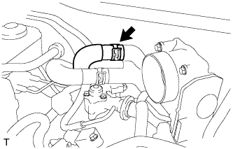
| 55. CONNECT INLET RADIATOR HOSE |
Install the clamp and connect the inlet radiator hose.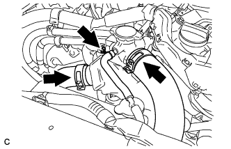
| 56. CONNECT OUTLET RADIATOR HOSE |
Install the clamp and connect the outlet radiator hose.
| 57. CONNECT RADIATOR RESERVOIR TANK HOSE |
Install the clamp and connect the reservoir tank hose.
| 58. CONNECT NO. 2 FUEL VAPOR FEED HOSE |
Install the clamp and connect the No. 2 fuel vapor feed hose.
| 59. CONNECT UNION TO CHECK VALVE HOSE |
Connect the hose to the surge tank.
| 60. INSTALL AIR CLEANER CASE SUB-ASSEMBLY |
Install the air cleaner case, clamp and 2 bolts.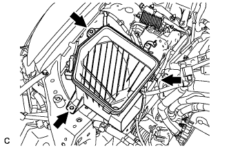
- Torque:
- 5.0 N*m{ 51 kgf*cm , 44 in.*lbf }
| 61. INSTALL AIR CLEANER CAP WITH AIR CLEANER HOSE |
Install the air cleaner cap with air cleaner hose assembly with the 4 clamps and hose clamp.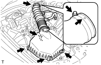
- HINT:
- Be sure to install the air cleaner assembly so that the screw part of the hose clamp is as shown in the illustration.
Install the VSV hose to the air cleaner hose.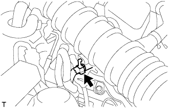
Connect the MAF meter connector and clamp to the air cleaner.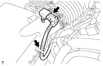
| 62. INSTALL NO. 1 INLET AIR CLEANER |
Install the inlet air cleaner with the bolt.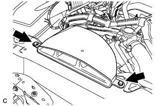
- Torque:
- 5.0 N*m{ 51 kgf*cm , 44 in.*lbf }
| 63. INSTALL PROPELLER SHAFT ASSEMBLY WITH CENTER BEARING |
- HINT:
- Click here.
| 64. INSTALL FRONT EXHAUST PIPE ASSEMBLY |
- HINT:
- Click here.
| 65. ADD ENGINE OIL |
Add new oil.
- Specification:
Item
Capacity
Drain and refill with oil filter change
6.3 liters (6.7 US qts, 5.5 Imp. qts)
Drain and refill without oil filter change
5.9 liters (6.2 US qts, 5.2 Imp. qts)
Dry fill
7.2 liters (7.6 US qts, 6.3 Imp. qts)
Install the oil filter cap.
| 66. CONNECT CABLE TO NEGATIVE BATTERY TERMINAL |
- Torque:
- 5.4 N*m{ 55 kgf*cm , 48 in.*lbf }
| 67. ADD ENGINE COOLANT |
Tighten all the plugs and fill the radiator with TOYOTA Super Long Life Coolant (SLLC).
- Torque:
- 13 N*m{ 130 kgf*cm , 9 ft.*lbf } for cylinder block drain cock plug
Add engine coolant.
- Specified capacity:
- 9.1 liters (9.6 US qts, 8.0 lmp. qts)
- HINT:
- TOYOTA vehicles are filled with TOYOTA SLLC at the factory. In order to avoid damage to the engine cooling system and other technical problems, only use TOYOTA SLLC or similar high quality ethylene glycol based non-silicate, non-amine, non-nitrite, non-borate coolant with long-life hybrid organic acid technology (coolant with long-life hybrid organic acid technology consists of a combination of low phosphates and organic acids).
- TOYOTA vehicles are filled with TOYOTA SLLC at the factory. In order to avoid damage to the engine cooling system and other technical problems, only use TOYOTA SLLC or similar high quality ethylene glycol based non-silicate, non-amine, non-nitrite, non-borate coolant with long-life hybrid organic acid technology (coolant with long-life hybrid organic acid technology consists of a combination of low phosphates and organic acids).
- Contact your TOYOTA dealer for further details.
- Contact your TOYOTA dealer for further details.
Slowly pour coolant into the radiator reservoir until it reaches the FULL line.
Press the inlet and outlet radiator hoses several times by hand, and then check the level of the coolant.
If the coolant level is low, add coolant.
Install the radiator cap and reservoir cap.
Bleed air from the cooling system.
- NOTICE:
- Before starting the engine to warm up the engine, turn the A/C switch OFF.
Warm up the engine until the thermostat opens. While the thermostat is open, circulate the coolant for several minutes.
- HINT:
- The thermostat open timing can be confirmed by pressing the inlet radiator hose by hand, and checking when the engine coolant starts to flow inside the hose.
- NOTICE:
- When pressing the radiator hoses:
- Wear protective gloves.
- Wear protective gloves.
- Be careful as the radiator hoses are hot.
- Be careful as the radiator hoses are hot.
- Keep your hands away from the radiator fans.
- Keep your hands away from the radiator fans.
Maintain the engine speed at 2,000 to 2,500 rpm.
Press the inlet and outlet radiator hoses several times by hand to bleed air.
- NOTICE:
- When pressing the radiator hoses:
- Wear protective gloves.
- Wear protective gloves.
- Be careful as the radiator hoses are hot.
- Be careful as the radiator hoses are hot.
- Keep your hands away from the radiator fans.
- Keep your hands away from the radiator fans.
Stop the engine, and wait until the engine coolant cools down to ambient temperature.
- NOTICE:
- Do not remove the radiator cap while the engine and radiator are still hot. Pressurized, hot engine coolant and steam may be released and cause serious burns.
Check the coolant level in the radiator reservoir.
If the coolant level is low, add SLLC to the radiator reservoir FULL line.
| 68. CHARGE REFRIGERANT |
Perform vacuum purging using a vacuum pump.
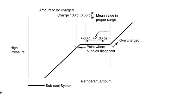
Charge refrigerant HFC-134a (R134a).
- Standard:
- 430 +- 30 g (15.17 +- 1.06 oz.)
- SST
- 07110-58060
(07117-58060, 07117-58070, 07117-58080, 07117-58090, 07117-78050, 07117-88060, 07117-88070, 07117-88080)
- NOTICE:
- Do not operate the cooler compressor before charging refrigerant as the cooler compressor will not work properly without any refrigerant, and will overheat.
- Do not operate the cooler compressor before charging refrigerant as the cooler compressor will not work properly without any refrigerant, and will overheat.
- Approximately 100 g (3.53 oz.) of refrigerant may need to be charged after bubbles disappear. The refrigerant amount should be checked by measuring its quantity, and not with the sight glass.
- Approximately 100 g (3.53 oz.) of refrigerant may need to be charged after bubbles disappear. The refrigerant amount should be checked by measuring its quantity, and not with the sight glass.
| 69. CHECK FOR FUEL LEAKS |
Connect the intelligent tester to the DLC3.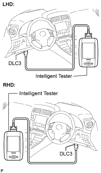
Turn the engine switch on (IG).
- NOTICE:
- Do not start the engine.
Push the intelligent tester main switch ON.
Select the following menus: Powertrain / Engine / Active Test / Control the Fuel Pump /Speed.
Check the fuel pump operation.
Check for pressure in the fuel inlet tube from the fuel line. Check that sound of fuel flowing in the fuel tank can be heard.
If no sound can be heard, check the integration relay, fuel pump, ECM and wiring connector.
Check for fuel leaks.
Check that there are no fuel leaks anywhere on the system after performing maintenance.
If there is a fuel leak, repair or replace parts as necessary.
| 70. CHECK FOR ENGINE COOLANT LEAKS |
 |
- NOTICE:
- Before performing each inspection, turn the A/C switch OFF.
- CAUTION:
- Do not remove the radiator cap while the engine and radiator are still hot. Pressurized, hot engine coolant and steam may be released and cause serious burns.
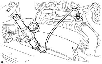
Fill the radiator with coolant and attach a radiator cap tester.
Warm up the engine.
Using a radiator cap tester, increase the pressure inside the radiator to 118 kPa (1.2 kgf*cm2, 17 psi), and check that the pressure does not drop.
If the pressure drops, check the hoses, radiator and water pump for leaks. If no external leaks are found, check the heater core, cylinder block and cylinder head.
| 71. CHECK FOR ENGINE OIL LEAKS |
| 72. CHECK FOR EXHAUST GAS LEAKS |
| 73. CHECK FOR LEAKAGE OF REFRIGERANT |
After recharging the refrigerant gas, check for refrigerant gas leakage using a halogen leak detector.
Perform the operation under the following conditions:
- Stop the engine.
- Secure good ventilation (the gas leak detector may react to volatile gases other than refrigerant, such as evaporated gasoline or exhaust gas).
- Repeat the test 2 or 3 times.
- Make sure that some refrigerant remains in the refrigeration system. When compressor is off: approximately 392 to 588 kPa (4 to 6 kgf*cm2 57 to 85 psi)
- Stop the engine.
Using a gas leak detector, check the refrigerant line for leakage.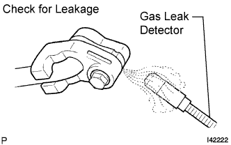
If a gas leak is not detected on the drain hose, remove the blower motor control (blower resistor) from the cooling unit. Insert the gas leak detector sensor into the unit and perform the test.
Disconnect the connector and leave the pressure switch on for approximately 20 minutes. Bring the gas leak detector close to the pressure switch and perform the test.
| 74. INSTALL FRONT WHEEL |
- Torque:
- 103 N*m{ 1,050 kgf*cm , 76 ft.*lbf }
| 75. PLACE FRONT WHEELS FACING STRAIGHT AHEAD |
| 76. ADJUST SHIFT LEVER POSITION |
Remove the nut and disconnect the shifting rod.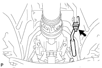
Turn the control shaft lever of the park/neutral position switch counterclockwise until it stops, and turn it clockwise 2 notches to set it to the N position.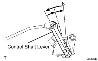
Move the shift lever to the N position and tighten the nut while lightly pushing the lever toward the R position.
- NOTICE:
- Do not push the shift lever too hard.
After adjustment, check that the shift lever moves smoothly and the shift lever and gear operate correctly.
| 77. CHECK SHIFT LEVER POSITION |
When shifting from the P to R position with the engine switch on (IG) and the brake pedal depressed, make sure that the shift lever moves smoothly and moves correctly into the position.
Start the engine and make sure that the vehicle moves forward when shifting from the N to D position and moves rearward when shifting to the R position.
If operation cannot be done as specified, inspect the park/neutral position switch assembly and check the shift lever assembly installation condition.
| 78. CHECK AND ADJUST FRONT WHEEL ALIGNMENT |
- HINT:
- Click here.
| 79. CHECK IGNITION TIMING |
Warm up the engine and stop the engine.
- NOTICE:
- A warmed up engine should have an engine coolant temperature of over 80°C (176°F), have an engine oil temperature of 60°C (140°F), and the engine rpm should be stabilized.
When using the intelligent tester: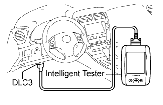
Connect the intelligent tester to the DLC3.
Start the engine and idle it.
Push the intelligent tester main switch ON.
Enter the following items: Powertrain / Engine and ECT / Data list / IGN Advance.
- Ignition timing:
- 5 to 15° BTDC at idle
- HINT:
- Refer to the intelligent tester operator's manual for further details.
When not using the intelligent tester:
Remove the V-bank cover sub-assembly.
Connect the tester probe of a timing light to the wire of the ignition connector for No. 1 cylinder.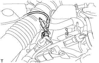
- NOTICE:
- Use a timing light which can detect the primary current.
Using SST, connect terminals TC and CG of the DLC3.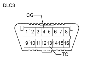
- SST
- 09843-18040
- NOTICE:
- Confirm the terminal numbers before connecting them. Connecting the wrong terminals can damage the engine.
- When checking the ignition timing, the transmission should be in neutral.
- Confirm the terminal numbers before connecting them. Connecting the wrong terminals can damage the engine.
Using a timing light, check the ignition timing.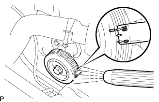
- Ignition timing:
- 8 to 12 BTDC at idle
Remove the SST from the DLC3.
Check the ignition timing.
- Ignition timing:
- 5 to 15° BTDC at idle
Check that the ignition timing advances immediately when the engine speed is increased.
Disconnect the timing light from the engine.
Install the V-bank cover sub-assembly.
| 80. CHECK ENGINE IDLE SPEED |
Warm up and stop the engine.
- NOTICE:
- A warmed up engine should have an engine coolant temperature of over 80°C (176°F) and an engine oil temperature of 60°C (140°F), and the engine rpm should be stabilized.
When using the intelligent tester:
Connect the intelligent tester to the DLC3.
- NOTICE:
- Switch off all accessories and A/C before connecting the intelligent tester.
Race the engine speed at 2,500 rpm for approx. 90 seconds.
Push the intelligent tester main switch ON.
Enter the following items: powertrain / Engine and ECT / Data list / Engine SPD.
- Idle speed:
- 650 to 750 rpm
- NOTICE:
- When checking the idle speed, the transmission should be in the neutral.
- HINT:
- Refer to the intelligent tester operator's manual for further details.
Disconnect the intelligent tester from the DLC3.
When not using the intelligent tester: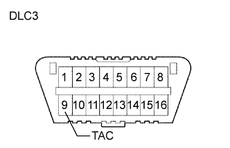
Using SST, connect the tachometer probe to terminal TAC of the DLC3.
- SST
- 09843-18040
- NOTICE:
- Confirm the terminal numbers before connecting them. Connecting the wrong terminals can damage the engine.
Race the engine speed at 2,500 rpm for approx. 90 seconds.
Check the idle speed.
- Idle speed (Transmission neutral position):
- 650 to 750 rpm
Disconnect the tachometer from the DLC3.
| 81. CHECK CO / HC |
- HINT:
- This check for determining whether or not the idle CO / HC complies with regulations.
Start the engine.
Keep the engine speed at 2,500 rpm for approx. 180 seconds.
Insert the CO / HC meter testing probe at least 40 cm (1.3 ft) into the tailpipe during idling.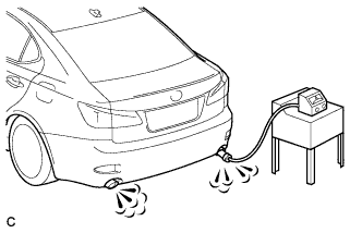
Immediately check CO / HC concentration at idle and / or 2,500 rpm.
- HINT:
- When performing the 2 mode (2,500 rpm and idle) test, follow the measurement order prescribed by the applicable local regulations.
- If the CO / HC concentration does not comply with regulations, troubleshoot in the order given below.
- When performing the 2 mode (2,500 rpm and idle) test, follow the measurement order prescribed by the applicable local regulations.
Check the A/F sensor and heated oxygen sensor operation.
See the table below for possible causes, then inspect and correct the applicable causes if necessary.
CO
HC
Symptom
Causes
Normal
High
Rough idle
- 1 .Faulty ignitions
- Incorrect timing
- Fouled, shorted or improperly gapped plugs
- 2. Leaky intake and exhaust valves
- 3. Leaky cylinder
Low
High
Rough idle
(Fluctuating HC reading)
- 1. Vacuum leaks
- PCV hose
- Intake manifold
- Throttle body
- 2. Lean mixture causing misfire
High
High
Rough idle
(Black smoke from exhaust)
- 1. Restricted air filter
- 2. Faulty fuel SFI system
- Faulty pressure
- Defective ECT sensor
- Faulty ECM
- Faulty injector
- Faulty throttle position sensor
- Faulty MAF sensor
- 1 .Faulty ignitions
| 82. CHECK ENGINE OIL LEVEL |
Warm up the engine, stop the engine and wait 5 minutes. The oil level should be between the dipstick's low level mark and full level mark.
If low, check for leakage and add oil up to the full level mark.- NOTICE:
- Do not fill with engine oil above the full level mark.
| 83. INSTALL ENGINE UNDER COVER REAR LH |
Install the engine under cover rear LH with the bolt.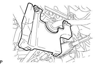
| 84. INSTALL ENGINE UNDER COVER REAR RH |
- HINT:
- Install the RH side following the same procedures as for the LH side.
| 85. INSTALL ENGINE UNDER COVER AIR GUIDE BRACKET |
Install the engine under cover air guide bracket with the 2 bolts.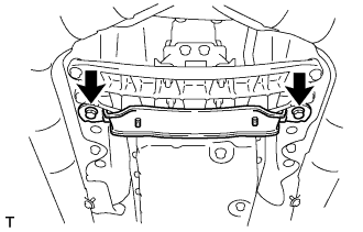
- Torque:
- 26 N*m{ 265 kgf*cm , 19 ft.*lbf }
| 86. INSTALL NO. 2 ENGINE UNDER COVER |
| 87. INSTALL ENGINE UNDER COVER |
| 88. INSTALL V-BANK COVER SUB-ASSEMBLY |
Engage the 2 clips on the front of the cover, and then engage the clip on the rear to install the V-bank cover.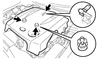
- NOTICE:
- Be sure to engage the clips securely.
- Do not apply excessive force or do not hit the cover to engage the clips. This may cause the cover to break.
- Be sure to engage the clips securely.
| 89. INSTALL ENGINE ROOM SIDE COVER LH |
Install the side cover with the 5 clips.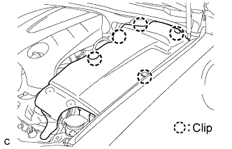
| 90. INSTALL ENGINE ROOM SIDE COVER RH |
Install the side cover with the 2 clips.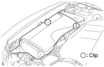
| 91. INSTALL COOL AIR INTAKE DUCT SEAL |
Install the intake duct seal with the 11 clips.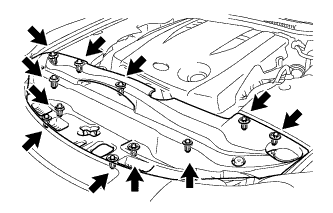
| 92. PERFORM INITIALIZATION |
Perform initialization (Click here).
- NOTICE:
- Certain systems need to be initialized after reconnecting the cable to the negative (-) battery terminal.