Television Camera ECU Communication Error
Circuit diagnosis
INSPECTION PROCEDURE
| 1. IDENTIFY THE COMPONENT SHOWN BY SUB-CODE |

Enter the diagnostic mode.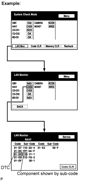

Press the "LAN Mon" switch to change to "LAN Monitor" mode.
Identify the component shown by the sub-code.
- HINT:
- "110 (multi-display)" is the component shown by the sub-code in the example shown in the illustration.
- The sub-code will be indicated by its physical address.
- For the component list, refer to "DIAGNOSIS DISPLAY DETAILED DESCRIPTION" (Click here).
- "110 (multi-display)" is the component shown by the sub-code in the example shown in the illustration.
| NEXT | |
 |
| 2. CHECK POWER SOURCE CIRCUIT OF COMPONENT SHOWN BY SUB-CODE |
Inspect the power source circuit of the component shown by the sub-code.If the power source circuit is operation normally, proceed to the next step.
Component Table: Component
Proceed to
Radio receiver (190)
Radio receiver power source circuit (Click here)
Gateway ECU (1C6)
Gateway ECU power source circuit (Click here)
Multi-display (110)
Multi-display power source circuit (Click here)
Navigation ECU (178)
Navigation ECU power source circuit (Click here)
Stereo component amplifier (440)
Stereo component amplifier power source circuit (Click here)
| NEXT | |
|
| 3. INSPECT RADIO RECEIVER |
Disconnect the radio receiver connectors.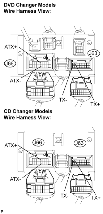
Measure the resistance according to the value(s) in the table below.
- Standard resistance:
Tester connection
Condition
Specified condition
ATX+ (J66-5) - ATX- (J66-15)
Always
60 to 80 Ω
TX+ (J63-9) - TX- (J63-10)
Always
60 to 80 Ω
|
|
||||

| OK | |
|
| 4. CHECK HARNESS AND CONNECTOR (TELEVISION CAMERA ECU - COMPONENT SHOWN BY SUB-CODE) |
- HINT:
- Start the check from the circuit that is near the component shown by the sub-code first.
- For details of the connectors, refer to "TERMINALS OF ECU" (Click here).
- Start the check from the circuit that is near the component shown by the sub-code first.
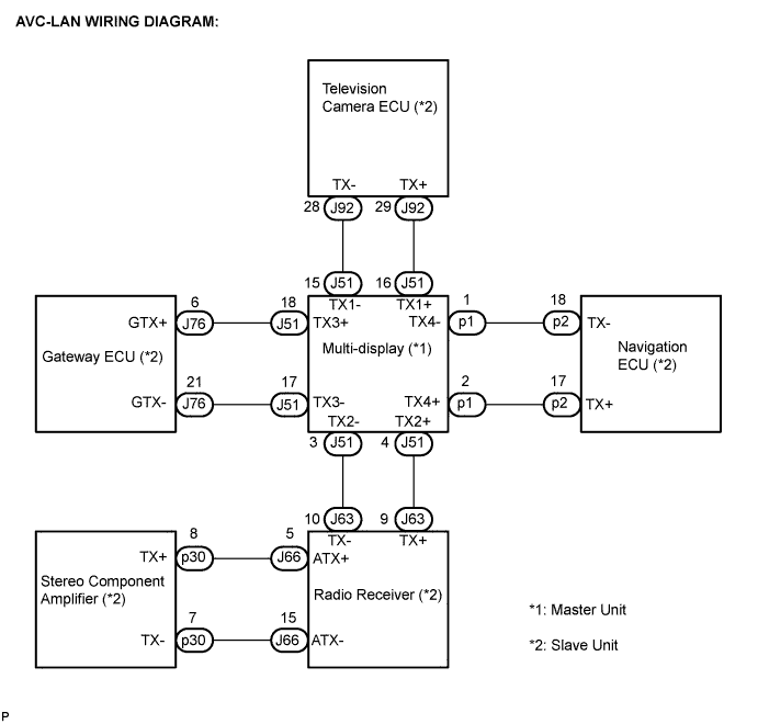
Referring to the AVC-LAN wiring diagram below, check the AVC-LAN circuit between the television camera ECU and the component shown by the sub-code.
Disconnect all connectors between the television camera ECU and the component shown by sub-code.
Check for an open or short in the AVC-LAN circuit between the television camera ECU and the component shown by the sub-code.
- OK:
- There is no open or short circuit.
|
|
||||
| OK | |
|
| 5. REPLACE COMPONENT SHOWN BY SUB-CODE |
Replace the component shown by the sub-code with a normal one and check if the same problem occurs again.
- OK:
- Same problem does not occur.
|
|
||||
| OK | ||
 |
||
| ||