| Last Modified: 11-27-2007 | 1.6 A | |
| Service Category: Brake | Section: Brake System | |
| Model Year: 2008 | Model: LX570 | Doc ID: RM00000171Q00HX |
| Title: BRAKE SYSTEM (OTHER): HYDRAULIC BRAKE BOOSTER: INSTALLATION (2008 LX570) | ||
INSTALLATION
1. INSTALL BRAKE BOOSTER GASKET
(a) Install a new brake booster gasket to the hydraulic brake booster assembly.
2. INSTALL HYDRAULIC BRAKE BOOSTER ASSEMBLY
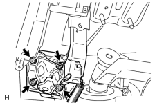
|
(a) Install the hydraulic brake booster assembly with the 4 nuts. Torque: 14 N·m (145 kgf·cm, 10 ft·lbf) |
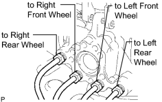
|
(b) Connect the 4 brake lines to the correct positions on the hydraulic brake booster assembly as shown in the illustration. |
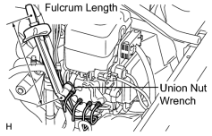
|
(c) Using a union nut wrench, tighten the 4 brake lines. Torque: 15 N·m (155 kgf·cm, 11 ft·lbf) Torque: 14 N·m (145 kgf·cm, 10 ft·lbf) HINT:
|
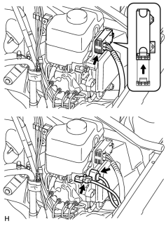
|
(d) Connect the 3 connectors to the hydraulic brake booster assembly. |
3. INSTALL PUSH ROD PIN

4. INSTALL DRIVER SIDE KNEE AIRBAG ASSEMBLY
5. INSTALL LOWER NO. 1 INSTRUMENT PANEL FINISH PANEL
6. INSTALL COWL SIDE TRIM BOARD LH
7. INSTALL NO. 1 INSTRUMENT PANEL UNDER COVER SUB-ASSEMBLY
8. INSTALL FRONT DOOR SCUFF PLATE LH
9. CONNECT CABLE TO NEGATIVE BATTERY TERMINAL
NOTICE:
When disconnecting the cable, some systems need to be initialized after the cable is reconnected
.
10. FILL RESERVOIR WITH BRAKE FLUID
11. BLEED BRAKE BOOSTER WITH ACCUMULATOR PUMP ASSEMBLY
12. BLEED BRAKE LINE
13. BLEED MASTER CYLINDER SOLENOID
14. CHECK BRAKE PEDAL HEIGHT
15. CHECK PEDAL FREE PLAY
16. CHECK PEDAL RESERVE DISTANCE
17. CHECK FLUID LEVEL IN RESERVOIR
18. INSPECT FOR BRAKE FLUID LEAK
19. INSPECT BRAKE MASTER CYLINDER OPERATION
(a) Inspect the brake master cylinder operation
.

|

|