| Last Modified: 11-27-2007 | 1.6 A | |
| Service Category: Vehicle Interior | Section: Heating/Air Conditioning | |
| Model Year: 2008 | Model: LX570 | Doc ID: RM0000017ZP00XX |
| Title: HEATING / AIR CONDITIONING: FRONT AIR CONDITIONING UNIT: INSTALLATION (2008 LX570) | ||
INSTALLATION
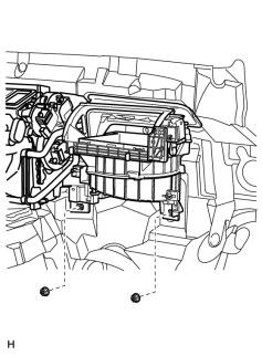
1. INSTALL AIR CONDITIONING UNIT ASSEMBLY
|
(a) Install the air conditioning unit with the 2 nuts. Torque: 9.8 N·m (100 kgf·cm, 87 in·lbf) |
2. INSTALL AIR CONDITIONING HOSE AND ACCESSORY (w/ Cool Box)
|
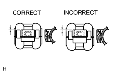
(a) Lubricate 2 new O-rings with compressor oil and install them to the air conditioning hose and accessory. Compressor oil: ND-OIL 8 or equivalent |
|
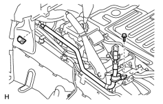
(b) Install the air conditioning hose and accessory with the piping clamp. NOTICE:
After connection, check the claw engagement of the piping clamp. |
(c) Install the bolt.
Torque: 9.8 N·m (100 kgf·cm, 87 in·lbf)
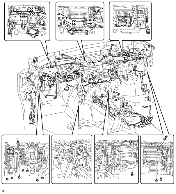
3. INSTALL INSTRUMENT PANEL REINFORCEMENT ASSEMBLY
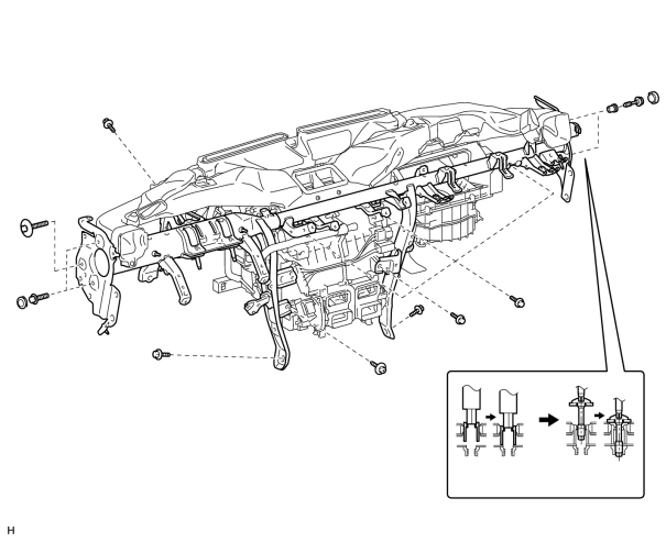
(a) Install the instrument panel reinforcement.
(1) Install the instrument panel reinforcement with the 7 bolts and screw.
Torque: 9.8 N·m (100 kgf·cm, 87 in·lbf)
Torque: 6.0 N·m (61 kgf·cm, 53 in·lbf)
(2) for Passenger Side:
Using a 12 mm hexagon wrench, install the 2 collars.
Torque: 18 N·m (184 kgf·cm, 13 ft·lbf)
(3) for Passenger Side:
Using a T40 "TORX" socket, install the 2 "TORX" bolts.
Torque: 18 N·m (184 kgf·cm, 13 ft·lbf)
(4) for Passenger Side:
Install the 2 caps.
(5) for Driver Side:
Install the 3 bolts.
Torque: 18 N·m (184 kgf·cm, 13 ft·lbf)
(6) for Driver Side:
Install the 3 caps.
(b) Attach the clamps to the wire harness and connect the connectors.
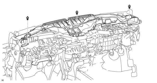
4. INSTALL HEATER TO REGISTER DUCT ASSEMBLY
(a) Attach the 2 claws to install the duct.
(b) Install the 3 clips.
5. INSTALL STEERING COLUMN ASSEMBLY
(a) Install the steering column
 .
.
6. INSTALL NO. 3 AIR DUCT SUB-ASSEMBLY
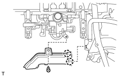
(a) Attach the 2 claws to install the duct.
(b) Install the clip.
7. INSTALL INSTRUMENT PANEL SUB-ASSEMBLY
(a) Install the instrument panel
.
8. INSTALL FRONT WIPER MOTOR AND BRACKET
(a) Install the front wiper motor and bracket
.
9. CONNECT HEATER WATER INLET HOSE AND HEATER WATER OUTLET HOSE
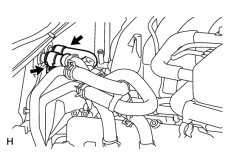
(a) Connect the 2 heater water hoses.
(b) Using pliers, grip the claws of the clips and slide the 2 clips.
10. CONNECT AIR CONDITIONING TUBE ASSEMBLY
|
(a) Remove the attached vinyl tape from the tubes. |
(b) Sufficiently apply compressor oil to 2 new O-rings and the fitting surface of the air conditioning tube assembly.
Compressor oil:
ND-OIL 8 or equivalent
(c) Install the 2 O-rings to the air conditioning tube assembly.
(d) Connect the air conditioning tube assembly.
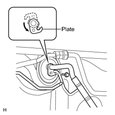
(e) Attach the plate as shown in the illustration and install the bolt.
Torque: 5.4 N·m (55 kgf·cm, 47 in·lbf)
11. CONNECT CABLE TO NEGATIVE BATTERY TERMINAL
NOTICE:
When disconnecting the cable, some systems need to be initialized after the cable is reconnected
.
12. CHECK SRS WARNING LIGHT
(a) Check the SRS warning light
.
13. ADD ENGINE COOLANT
(a) Add engine coolant
.
14. CHARGE REFRIGERANT
15. WARM UP ENGINE
16. CHECK FOR ENGINE COOLANT LEAK
17. CHECK FOR REFRIGERANT GAS LEAK
(a) Check for refrigerant gas leak
.
18. INSTALL UPPER RADIATOR SUPPORT SEAL
19. INSTALL ENGINE ROOM SIDE COVER LH
20. INSTALL ENGINE ROOM SIDE COVER RH
21. INSTALL NO. 1 ENGINE UNDER COVER SUB-ASSEMBLY
22. INSTALL FRONT FENDER SPLASH SHIELD SUB-ASSEMBLY LH
23. INSTALL FRONT FENDER SPLASH SHIELD SUB-ASSEMBLY RH

|

|