| Last Modified: 11-27-2007 | 1.6 A | |
| Service Category: Steering | Section: Steering Linkage/Steering Gear | |
| Model Year: 2008 | Model: LX570 | Doc ID: RM0000039SX004X |
| Title: STEERING GEAR / LINKAGE: STEERING LINKAGE: INSTALLATION (2008 LX570) | ||
INSTALLATION
1. INSTALL POWER STEERING LINK ASSEMBLY
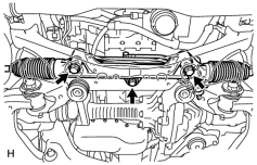
(a) Install the power steering link with the 3 bolts and 3 nuts.
Torque: 120 N·m (1224 kgf·cm, 89 ft·lbf)
HINT:
Hold the bolts and tighten the nuts to install the power steering link.
NOTICE:
Align the center bush so that the protrusion aligns with the longitudinal axis of the vehicle.
2. INSTALL FRONT SUSPENSION REBOUND STOPPER SUB-ASSEMBLY LH

3. INSTALL FRONT SUSPENSION REBOUND STOPPER SUB-ASSEMBLY RH
4. INSTALL PRESSURE FEED TUBE ASSEMBLY
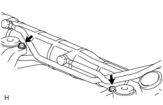
(a) Install the pressure feed tube clamp with the 2 bolts.
Torque: 18 N·m (184 kgf·cm, 13 ft·lbf)
|
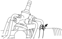
(b) Install the clamp and connect the pressure feed tube (return tube side) to the power steering link. |
|
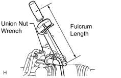
(c) Using a union nut wrench, connect the pressure feed tube (pressure feed tube side) to the power steering link. Torque: 44 N·m (449 kgf·cm, 32 ft·lbf) Torque: 40 N·m (409 kgf·cm, 30 ft·lbf) HINT:
|
5. INSTALL TIE ROD END SUB-ASSEMBLY LH
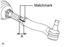
(a) Align the matchmarks of the tie rod and rack end, and temporarily install the tie rod with the lock nut.
HINT:
After adjusting toe-in, tighten the lock nut.
Torque: 82 N·m (836 kgf·cm, 60 ft·lbf)
(b) Check that length A is the same as the length measured previously.
6. INSTALL TIE ROD END SUB-ASSEMBLY RH
HINT:
Use the same procedures described for the RH side.
7. INSTALL STEERING RACK BOOT PROTECTOR LH
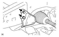
(a) Install the steering rack boots protector with the 2 bolts.
Torque: 29 N·m (296 kgf·cm, 21 ft·lbf)
8. INSTALL STEERING RACK BOOT PROTECTOR RH
HINT:
Use the same procedures described for the RH side.
9. CONNECT TIE ROD END SUB-ASSEMBLY LH
10. CONNECT TIE ROD END SUB-ASSEMBLY RH
HINT:
Use the same procedures described for the RH side.
11. CONNECT NO. 2 STEERING INTERMEDIATE SHAFT
12. INSTALL FRONT STABILIZER BAR
13. TEMPORARILY INSTALL FRONT STABILIZER LINK ASSEMBLY RH
14. TEMPORARILY INSTALL FRONT STABILIZER LINK ASSEMBLY LH
15. TIGHTEN FRONT NO. 1 STABILIZER BRACKET LH
16. TIGHTEN FRONT NO. 1 STABILIZER BRACKET RH
17. STABILIZE SUSPENSION
18. TIGHTEN FRONT STABILIZER LINK ASSEMBLY LH
19. TIGHTEN FRONT STABILIZER LINK ASSEMBLY RH
20. BLEED POWER STEERING FLUID
21. CHECK POWER STEERING FLUID LEVEL
22. CHECK FOR POWER STEERING FLUID LEAK
23. INSTALL FRONT WHEELS
24. PLACE FRONT WHEELS FACING STRAIGHT AHEAD
HINT:
Perform this procedure with the front of the vehicle jacked up.
25. PERFORM VEHICLE HEIGHT OFFSET CALIBRATION
(a) Perform the vehicle height offset calibration
.
26. ADJUST FRONT WHEEL ALIGNMENT
(a) Adjust the front wheel alignment
.
27. ADJUST HEADLIGHT ASSEMBLY
(a) Adjust the headlight
.

|

|