| Last Modified: 11-27-2007 | 1.6 A | |
| Service Category: Vehicle Interior | Section: Heating/Air Conditioning | |
| Model Year: 2008 | Model: LX570 | Doc ID: RM000003A3O007X |
| Title: HEATING / AIR CONDITIONING: REAR AIR CONDITIONING UNIT: INSTALLATION (2008 LX570) | ||
INSTALLATION
1. INSTALL REAR COOLING UNIT ASSEMBLY
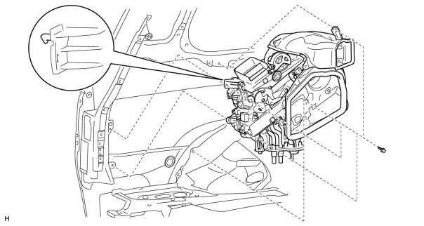
(a) Install the rear cooling unit as shown in the illustration.
|
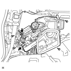
(b) Install the 4 bolts. Torque: 5.4 N·m (55 kgf·cm, 48 in·lbf) |
(c) Connect the 2 connectors.
2. INSTALL REAR ROOF NO. 1 AIR DUCT
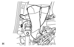
(a) Install the duct with the clip.
|
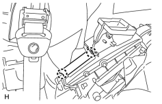
(b) Attach the 2 claws to install the cooler plate. |
3. CONNECT AIR CONDITIONER TUBE AND ACCESSORY ASSEMBLY
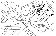
(a) Remove the attached vinyl tape from the pipe.
(b) Sufficiently apply compressor oil to 2 new O-rings and the fitting surface of the air conditioner tube and accessory assembly.
(c) Install the 2 O-rings to the air conditioner tube and accessory assembly.
(d) Connect the air conditioner tube and accessory assembly.
(e) Install the 2 nuts.
Torque: 5.4 N·m (55 kgf·cm, 48 in·lbf)
(f) Connect the heater water inlet hose and heater water outlet hose.
(g) Using pliers, grip the claws of the clips and slide the 2 clips.
4. INSTALL FRONT QUARTER TRIM PANEL ASSEMBLY LH

5. INSTALL REAR SEAT COVER CAP (for Semi Power Seat)
6. INSTALL REAR DOOR SCUFF PLATE LH
7. INSTALL REAR STEP COVER
8. INSTALL REAR FLOOR MAT REAR SUPPORT PLATE
9. INSTALL REAR NO. 2 SEAT ASSEMBLY LH
(a) Install the rear No. 2 seat assembly
.
10. INSTALL REAR NO. 2 SEAT ASSEMBLY RH
(a) Install the rear No. 2 seat assembly
.
11. CONNECT CABLE TO NEGATIVE BATTERY TERMINAL
NOTICE:
When disconnecting the cable, some systems need to be initialized after the cable is reconnected
.
12. ADD ENGINE COOLANT
13. CHARGE REFRIGERANT
14. WARM UP ENGINE
15. CHECK FOR ENGINE COOLANT LEAKS
16. CHECK FOR REFRIGERANT GAS LEAK
17. CHECK SRS WARNING LIGHT
(a) Check the SRS warning light
.
18. INSTALL UPPER RADIATOR SUPPORT SEAL
19. INSTALL ENGINE ROOM SIDE COVER LH
20. INSTALL ENGINE ROOM SIDE COVER RH
21. INSTALL NO. 1 ENGINE UNDER COVER SUB-ASSEMBLY
22. INSTALL FRONT FENDER SPLASH SHIELD SUB-ASSEMBLY LH
23. INSTALL FRONT FENDER SPLASH SHIELD SUB-ASSEMBLY RH

|

|