Electronic Control System Circuit Diagram
Precautions: General safety (00)
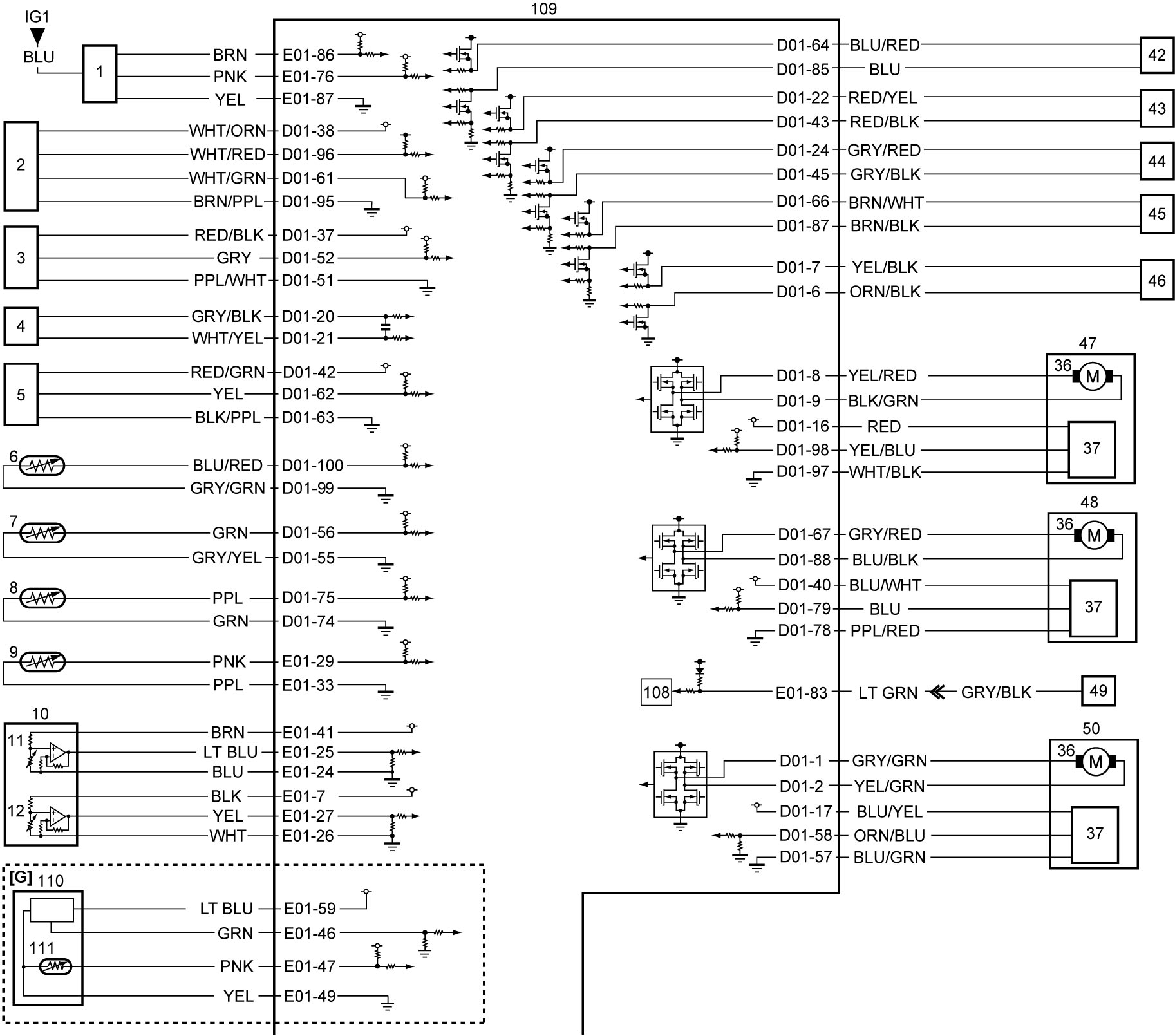
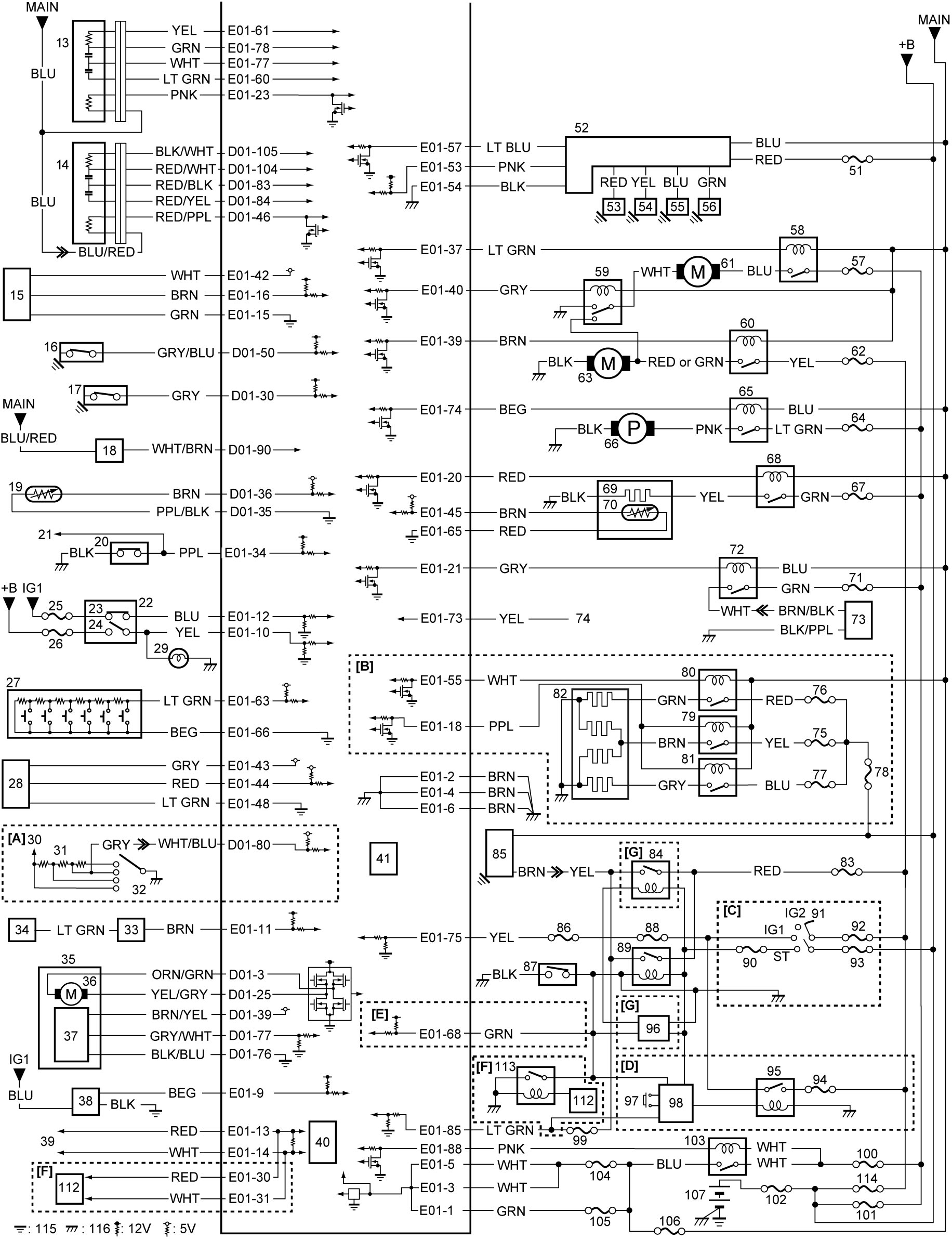
| [A]: | Manual A/C and Non-A/C model | 35. | Turbocharger actuator | 76. | “SUB HTR2” fuse |
| [B]: | With additional heater | 36. | Motor | 77. | “SUB HTR3” fuse |
| [C]: | Ignition switch model | 37. | Position sensor | 78. | “FL” fuse |
| [D]: | Keyless push start model | 38. | Fuel filter water detection sensor | 79. | Additional heater relay No.1 |
| [E]: | Keyless push start – M/T model | 39. | To other control modules and sensors connected by CAN | 80. | Additional heater relay No.2 |
| [F]: | Twin clutch system model | 40. | CAN driver | 81. | Additional heater relay No.3 |
| [G]: | Non-ENG A-STOP model | 41. | Barometric pressure sensor | 82. | Additional heater |
| 1. | MAF sensor with IAT sensor-1 | 42. | Fuel injector No.1 | 83. | “ST” fuse |
| 2. | Boost pressure sensor with IAT sensor-2 | 43. | Fuel injector No.2 | 84. | ST2 relay |
| 3. | CMP sensor | 44. | Fuel injector No.3 | 85. | Starting motor |
| 4. | CKP sensor | 45. | Fuel injector No.4 | 86. | “IG SIG” fuse |
| 5. | Fuel pressure sensor | 46. | Fuel flow actuator | 87. | CPP switch No.1 (M/T model) |
| 6. | ECT sensor | 47. | Inlet throttle valve | 88. | “IG COIL” fuse |
| 7. | EGT sensor-1 | 48. | EGR-1 valve | 89. | Starting motor control relay |
| 8. | EGT sensor-2 | 49. | Generator | 90. | “ST SIG” fuse |
| 9. | EGT sensor-3 | 50. | EGR-2 valve | 91. | Ignition switch |
| 10. | APP sensor | 51. | “FL2” fuse | 92. | “IG1” fuse |
| 11. | APP sensor (main) | 52. | Glow plug control module | 93. | “IG2” fuse |
| 12. | APP sensor (sub) | 53. | Glow plug No.1 | 94. | “IGN” fuse |
| 13. | A/F sensor-1 | 54. | Glow plug No.2 | 95. | IG1 relay |
| 14. | A/F sensor-2 | 55. | Glow plug No.3 | 96. | ENG A-STOP control module |
| 15. | DPF® differential pressure sensor | 56. | Glow plug No.4 | 97. | Engine switch |
| 16. | Oil pressure switch-1 | 57. | “RDTR” fuse | 98. | Keyless start control module |
| 17. | Oil pressure switch-2 | 58. | Radiator cooling fan relay No.1 | 99. | “ST SIG” fuse |
| 18. | VDOP solenoid valve | 59. | Radiator cooling fan relay No.2 | 100. | “FI” fuse (30 A) |
| 19. | EGT sensor-4 | 60. | Radiator cooling fan relay No.3 | 101. | “FL3” fuse |
| 20. | CPP switch No.2 (M/T model) | 61. | Radiator cooling fan motor | 102. | “FL1” fuse |
| 21. | To ENG A-STOP control module | 62. | “RDTR2” fuse | 103. | Main relay |
| 22. | Brake light switch / brake switch | 63. | Radiator cooling sub fan motor | 104. | “INJ DRV” fuse |
| 23. | Brake switch | 64. | “F/P” fuse | 105. | “FI2” fuse |
| 24. | Brake light switch | 65. | Fuel pump relay | 106. | “FI” fuse (15 A) |
| 25. | “CRUISE” fuse (cruise control model) | 66. | Fuel pump | 107. | Battery |
| 26. | “STOP” fuse | 67. | “FUEL HTR” fuse | 108. | LIN driver |
| 27. | Cruise control switch (cruise control model) | 68. | Fuel heater relay | 109. | ECM |
| 28. | A/C refrigerant pressure sensor | 69. | Fuel heater | 110. | Electric load current sensor |
| 29. | Brake light | 70. | Fuel temperature sensor | 111. | Battery temperature sensor |
| 30. | To blower motor | 71. | “CPRSR” fuse (A/C model) | 112. | TCM |
| 31. | Blower speed resistor | 72. | A/C compressor relay (A/C model) | 113. | ST3 relay |
| 32. | Blower speed selector | 73. | A/C compressor (A/C model) | 114. | “FL5” fuse |
| 33. | MAX hot switch (if equipped) | 74. | Not connected | 115. | Engine ground |
| 34. | HVAC control unit | 75. | “SUB HTR” fuse | 116. | Ground |
Terminal Arrangement of ECM Connector
NOTE:
For circuit name and terminal voltage, refer to Inspection of ECM and Its Circuits:D16AA.
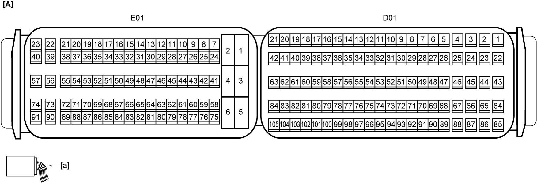
| [A]: | ECM connector (View: [a]) |