Piston, Piston Ring and Connecting Rod Removal and Installation
Precautions: General safety (00)
NOTE:
•All parts to be installed must be perfectly clean.
•Connecting rods, connecting rod bearings, connecting rod bearing caps, pistons and piston rings are in combination sets. Do not disturb such combination and check that each part goes back to where it came from, when installing.
•Connecting rods, connecting rod bearings, connecting rod bearing caps, pistons and piston rings are in combination sets. Do not disturb such combination and check that each part goes back to where it came from, when installing.
Removal
1)Remove engine assembly. 
2)Remove cylinder head.
3)Remove oil pan.
4)Mark cylinder numbers on all pistons using silver pencil or quick drying paint for installation.
NOTE:
Connecting rod and connecting rod bearing cap are stamped with numbers corresponding with each cylinder number. If stamped numbers cannot be found, mark each cylinder number on them.
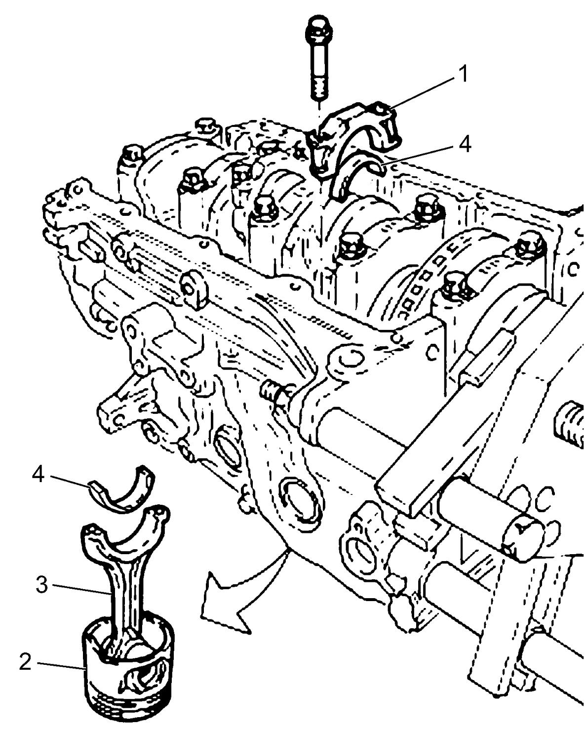
5)Remove connecting rod bearing caps (1).
6)Remove carbon deposit from top of cylinder bore before removing piston from cylinder.
7)Push piston (2) and connecting rod (3) assembly out through the top of cylinder bore.
8)Remove connecting rod bearings (4) from connecting rod and connecting rod bearing cap, if necessary.

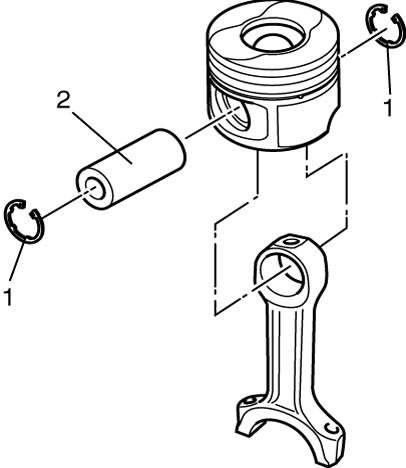
9)Remove piston pin from connecting rod as follows.
a)Remove piston pin circlips (1).
b)Take out piston pin (2).
10)Using piston ring expander, remove two compression rings (1st and 2nd) and oil ring from piston, if necessary.
Installation
1)Remove carbon deposit from piston head and ring grooves using a suitable tool.
2)Install piston rings to piston noting the following points, if removed.
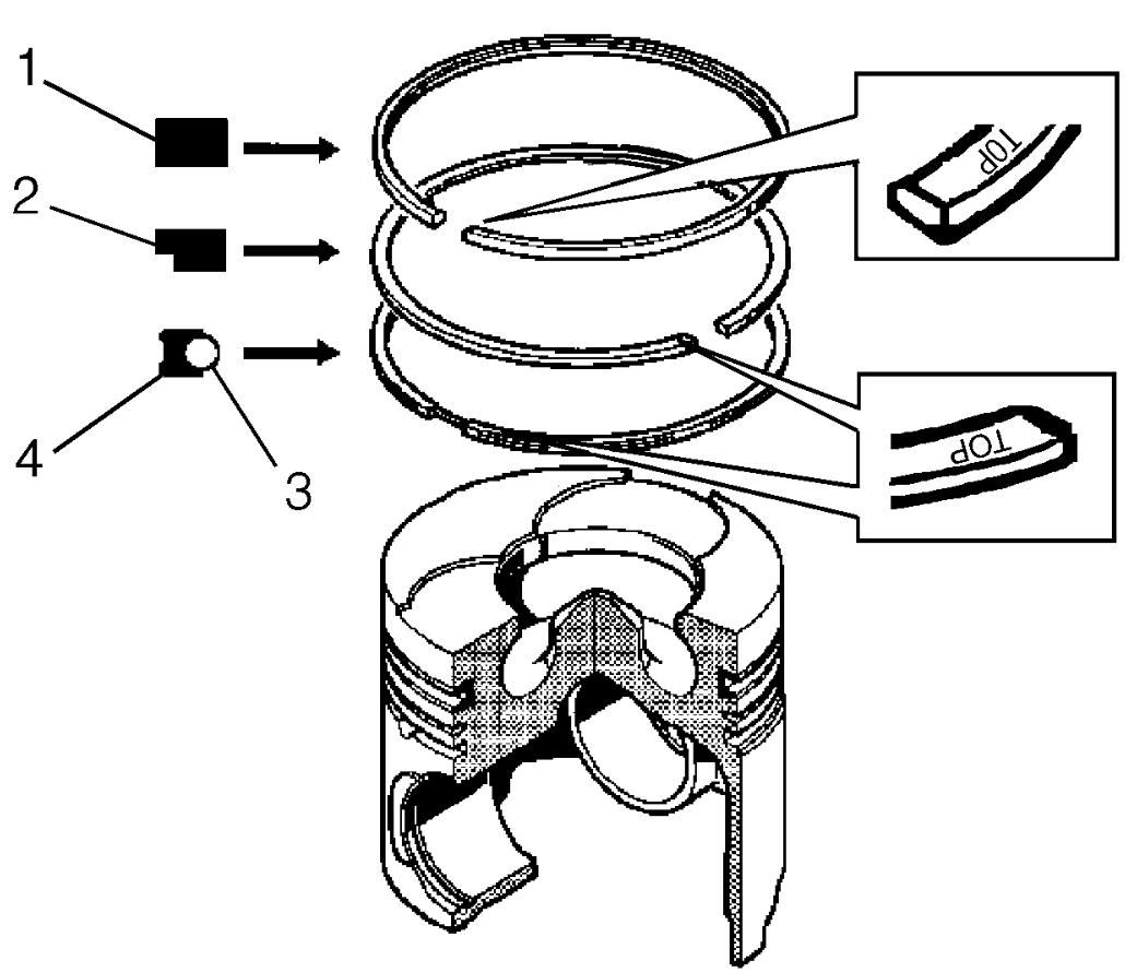
•1st, 2nd and oil rings have “TOP” mark respectively. When installing these piston rings to piston, direct marked side of each ring toward top of piston as shown in figure.
•Distinguish 1st ring (1) from 2nd ring (2) referring to the following figure.
•When installing oil ring, install spring ring (3) first and then rail (4).
•Distinguish 1st ring (1) from 2nd ring (2) referring to the following figure.
•When installing oil ring, install spring ring (3) first and then rail (4).
3)Assemble piston and connecting rod with piston pin as follows.
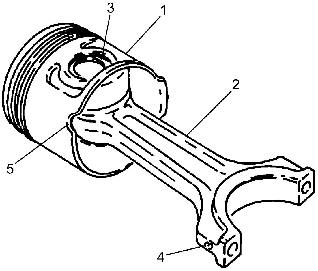
a)Apply engine oil to piston pin, piston pin hole of piston (1) and connecting rod (2).
b)Fit connecting rod to piston aligning “groove” (5) of piston with cylinder number (4) of connecting rod.
c)Insert piston pin to piston and connecting rod.
d)Install new piston pin circlips (3).
4)Apply engine oil to pistons, piston rings, cylinder walls, connecting rod bearings and crankshaft pins.
NOTICE:
If oil is present between the bearing’s outside surface and the connecting rod surface, the bearing could heat up to very high temperature, resulting in seizure.
Thoroughly wipe off any trace of oil that is present between the bearing’s outside surface and the connecting rod surface.
5)Install connecting rod bearing to connecting rod bearing cap and connecting rod as follows.
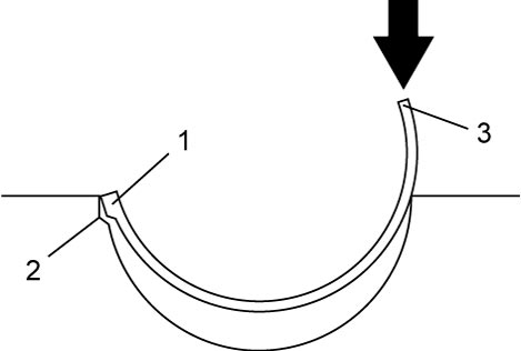
a)Fit tab (1) of connecting rod bearing to groove (2) of connecting rod and connecting rod bearing cap.
b)Press bearing end (3) until it becomes flush with connecting rod and connecting rod bearing cap mating surfaces.
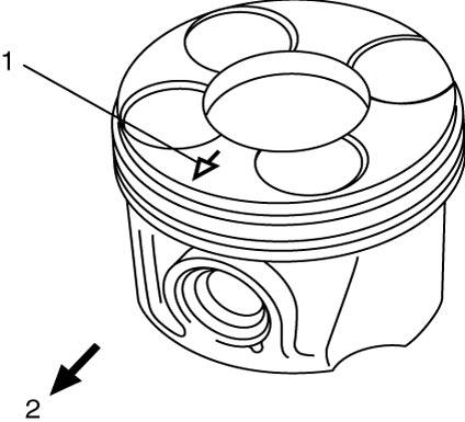
6)When installing piston and connecting rod assembly into cylinder bore, direct arrow mark (1) on piston head to crankshaft pulley side (2).
7)Distribute end gaps of three piston rings (1st, 2nd and oil rings) as shown in figure.
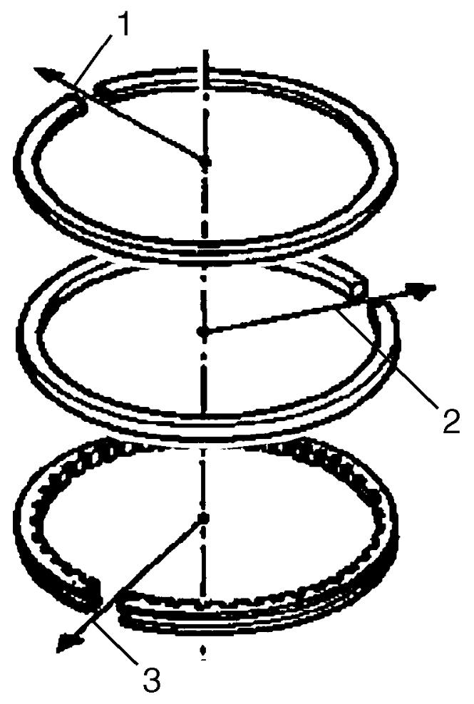
| 1. | 1st ring end gap | 3. | Oil ring end gap |
| 2. | 2nd ring end gap |
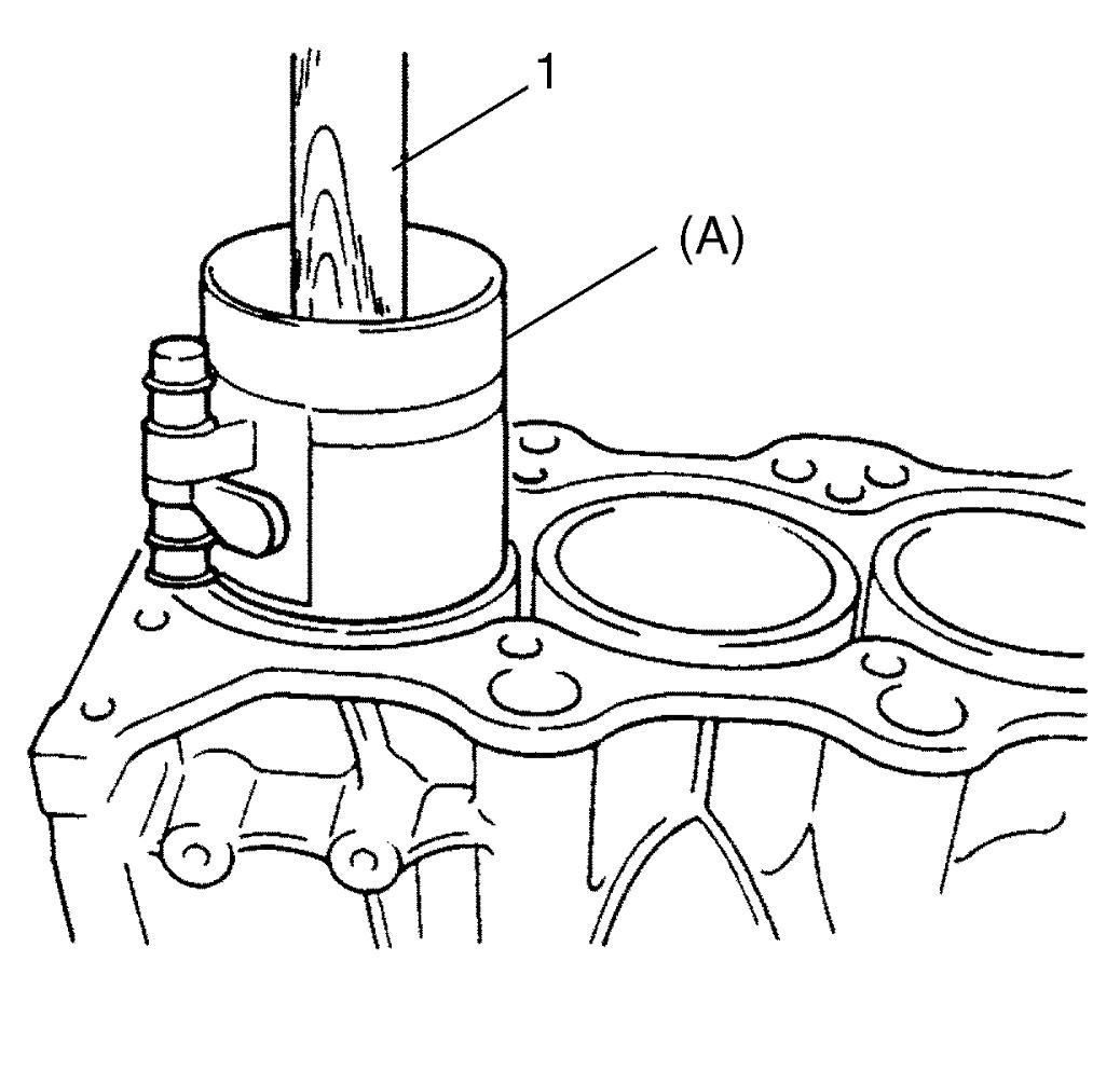
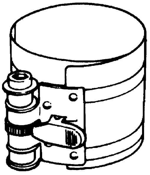
8)Install piston and connecting rod assembly into applicable cylinder bore conforming cylinder number on connecting rod. Use special tool to compress piston rings. Guide connecting rod into place on crankshaft. Using a hammer handle (1), tap piston head to install piston into bore. Hold ring compressor firmly against cylinder block until all piston rings enter the cylinder bore.
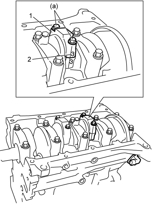
9)Install connecting rod bearing cap (1), conforming number (2) on bearing cap to number on connecting rod, and tighten new connecting rod bearing cap bolts as follows.
a)Tighten all new connecting rod bearing cap bolts to 25 N·m (2.5 kgf-m, 18.5 lbf-ft) evenly and gradually.
10)Install oil pan.
11)Install cylinder head.
12)Install engine assembly.