Valve and Cylinder Head Assembly Removal and Installation
Precautions: General safety (00)
Removal
1)Remove engine assembly. 
2)Remove glow plugs.
3)Remove camshaft housing assembly.
4)Remove turbocharger with exhaust manifold.
5)Remove intake manifold.
6)Remove EGR-1 valve mounting.
7)Remove water pump.
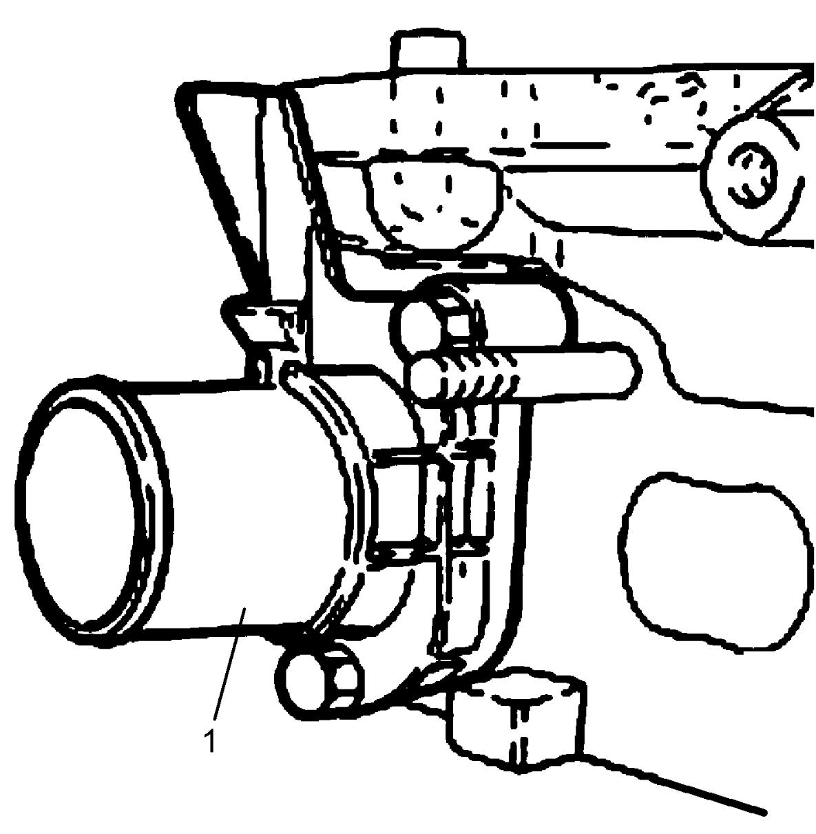
8)Remove water pump return connector (1) and gasket from cylinder head.

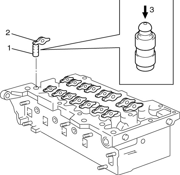
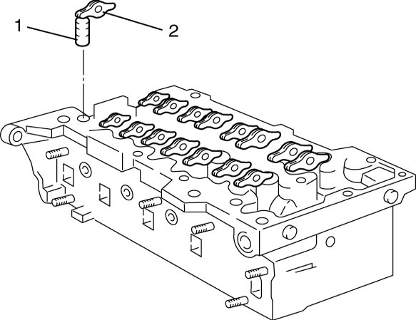
9)Remove valve lash adjuster (1) and valve rocker arm (2).
NOTE:
•To prevent leakage of inside oil, do not apply force (3) to valve lash adjuster.
•Immerse removed valve lash adjusters in clean engine oil and keep them as they are until their reinstallation to prevent entering of air in the adjusters.
•Immerse removed valve lash adjusters in clean engine oil and keep them as they are until their reinstallation to prevent entering of air in the adjusters.
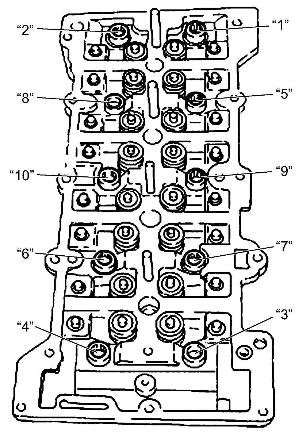
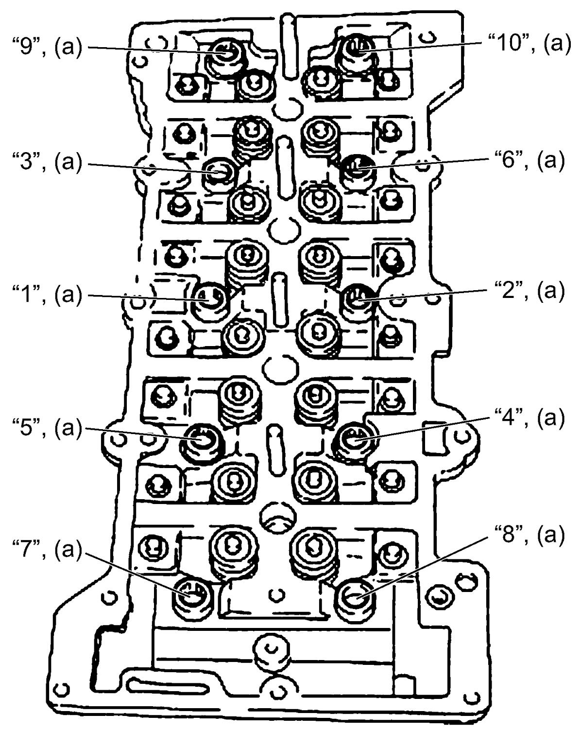
10)Loosen cylinder head bolts in numerical order (“1” – “10”) evenly and gradually.
11)Remove cylinder head and gasket from cylinder block.
12)Remove dowel pins (1), if necessary.
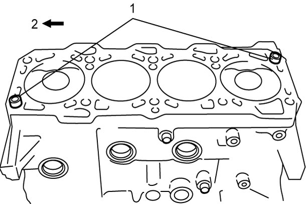
| 2. | Flywheel side |
13)Check all around cylinder head for any other parts required to be removed or disconnected and remove or disconnect them, if any.
Installation
1)Clean mating surfaces of cylinder head and cylinder block.
2)Install dowel pins (1) to cylinder block, if removed.
| 2. | Flywheel side |
3)Select applicable cylinder head gasket as follows.
NOTICE:
Failure to take proper precautions when handling the cylinder head gasket may lose its original sealing performance and lead damage to the engine.
•Keep the gasket sealed in its container until it is installed.
•Do not touch or lubricate the gasket surface.
•Do not touch or lubricate the gasket surface.
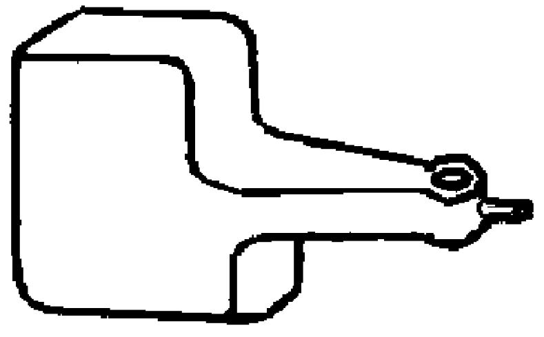
a)With piston (1) protruded condition from cylinder block (2) at TDC position as shown in figure, measure the protrusion “a” at two points [a] and [b] using special tool and dial gauge, and take an average. Repeat this procedure in all pistons. If measured average protrusion “a” is not as specified, check connecting rod referring to “Connecting Rod” under Piston Pin and Connecting Rod Inspection:D16AA.
If connecting rod is normal, replace piston and/or cylinder block.
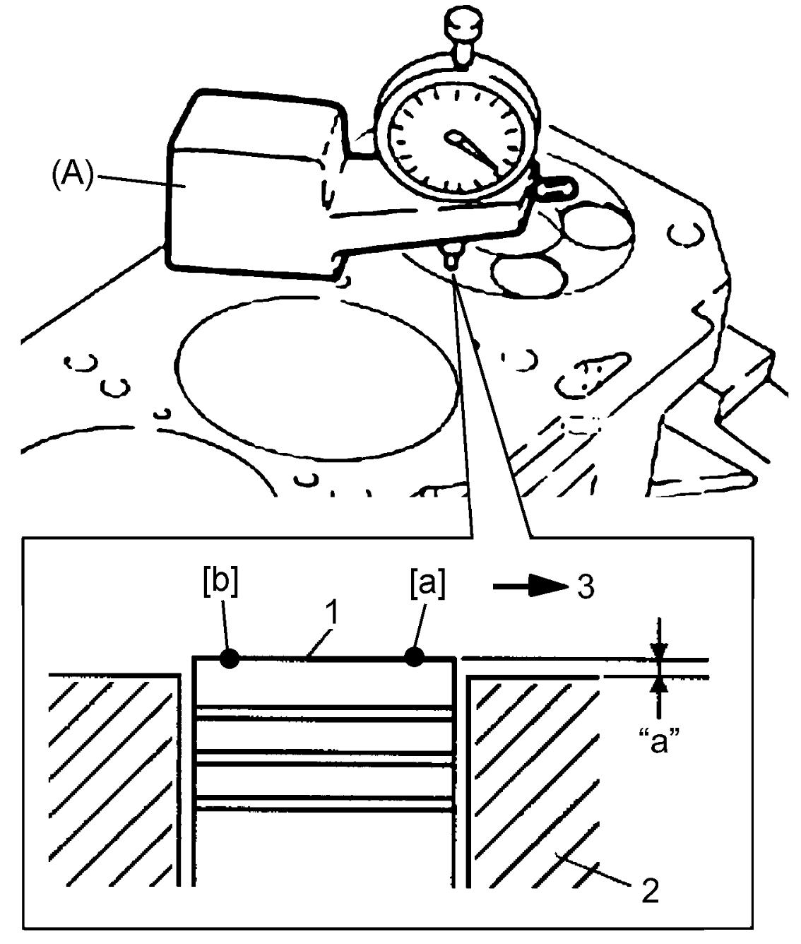
If connecting rod is normal, replace piston and/or cylinder block.
Average of piston protrusion
“a”: 0.020 – 0.295 mm (0.0008 – 0.0116 in.)
| 3. | Timing belt side |
b)Select new cylinder head gasket from the following three types according to value of protrusion “a” measured at Step a).
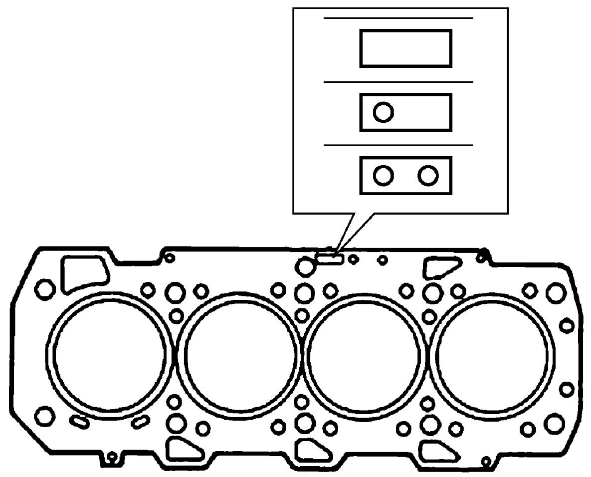
Cylinder head gasket specification
| Number of holes | Gasket thickness | Available piston protrusion |
|---|---|---|
| 0 | 0.770 – 0.870 mm (0.0303 – 0.0342 in.) |
0.020– 0.100 mm (0.0008 – 0.0039 in.) |
| 1 | 0.870 – 0.970 mm (0.0342 – 0.0381 in.) |
0.101 – 0.200 mm (0.0039 – 0.0078 in.) |
| 2 | 0.970 – 1.070 mm (0.0381 – 0.0421 in.) |
0.201 – 0.295 mm (0.0079 – 0.0116 in.) |
4)Install new cylinder head gasket to cylinder block.
5)Install cylinder head to cylinder block.
6)Tighten new cylinder head bolts as follows.
a)Tighten new cylinder head bolts to 66 N·m (6.7 kgf-m, 49.0 lbf-ft) in numerical order (“1” – “10”) evenly and gradually.
b)In the same manner as in Step a), retighten them 90°.
c)Repeat Step b).
7)Apply engine oil around valve lash adjuster (1) and valve rocker arm (2), and install them to cylinder head.
8)Install water pump return connector (1) with new gasket to cylinder head.
9)Install water pump.
10)Install EGR-1 valve mounting.
11)Install intake manifold.
12)Install turbocharger with exhaust manifold.
13)Install camshaft housing assembly.
14)Install glow plugs.
15)Install engine assembly.