ESP® Warning Light Comes ON Steady
Precautions: Precautions for ESP® · Precautions for Diagnosing Trouble · Test with Speedometer Tester or Other Equipment · Precautions for Brakes · General safety (00)
Circuit Diagram
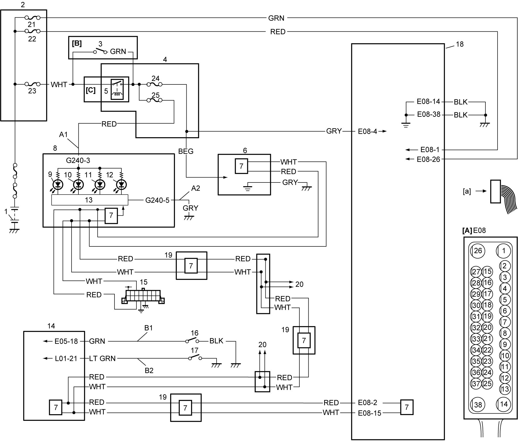
| [A]: | ESP® hydraulic unit / control module assembly connector (View: [a]) | 8. | Combination meter | 18. | ESP® hydraulic unit / control module assembly |
| [B]: | Ignition switch model | 9. | ESP® OFF light | 19. | Other control modules (if equipped) |
| [C]: | Keyless push start model | 10. | ESP® warning light | 20. | To other control modules by CAN |
| 1. | Battery | 11. | ABS warning light | 21. | “ABS” fuse (25A) |
| 2. | Relay box | 12. | EBD warning light (brake warning light) | 22. | “ABS2” fuse |
| 3. | Ignition switch | 13. | CPU (combination meter) | 23. | “IGN” fuse |
| 4. | J/B | 14. | BCM | 24. | “ABS” fuse (10A) |
| 5. | IG1 relay | 15. | DLC | 25. | “MTR” fuse |
| 6. | Steering angle sensor | 16. | Brake fluid level switch | ||
| 7. | CAN driver | 17. | Parking brake switch |
Circuit Description
Refer to “Circuit Description” under ESP® Warning Light Does Not Come ON after Setting Ignition “ON”.
Troubleshooting
| Step | Action | Yes | No |
|---|---|---|---|
| 1 |
ESP® control module connector check
1)Check for proper connection to “E08” connector.
Is connection in good condition?
|
Go to Step 2.
|
Connect connector securely.
|
| 2 |
DTC check
1)Perform DTC Check.
Is DTC(s) detected?
|
Go to applicable DTC troubleshooting.
|
Go to Step 3.
|
| 3 |
ESP® control module power supply and ground circuit check
1)Check ESP® control module power supply circuit and ground circuit.

Are the circuits in good condition?
|
Go to Step 4.
|
Repair or replace defective wire harness.
|
| 4 |
Combination meter check
1)Replace combination meter.
2)Set ignition “ON”.
Does ESP® warning light stay on?
|
Replace ESP® hydraulic unit / control module assembly and recheck warning light operation.
|
End.
|