DTC B1060-1B
Precautions: Precautions for Air Bag System Service · Precautions for Handling and Storage of Air Bag System Components · Precautions for Disposal of Air Bag and Seat Belt Pretensioner · Precautions for Restraint · General safety (00)
DTC Detecting Condition and Trouble Area
| DTC detecting condition | Trouble area |
|---|---|
|
B1060-1B: Driver Air Bag (1st stage) Circuit High Resistance Driver air bag (inflator) module circuit resistance is more than specified range. |
•Driver air bag (inflator) module circuit
•Contact coil assembly •Driver air bag (inflator) module •SDM |
Circuit Diagram
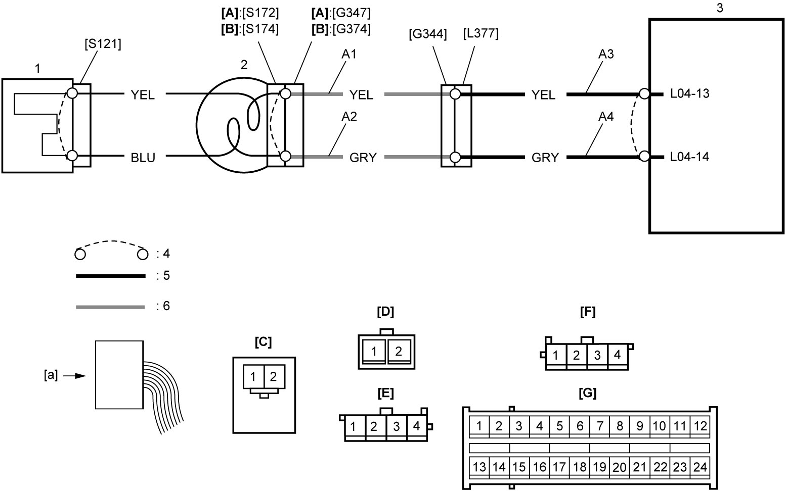
| [A]: | Without cruise control system | [G]: | “L04” connector (View: [a]) | 2. | Contact coil assembly |
| [B]: | With cruise control system | A1: | Driver air bag (inflator) module deployment signal output circuit | 3. | SDM |
| [C]: | “S121” connector (View: [a]) | A2: | Driver air bag (inflator) module deployment signal ground circuit | 4. | Shorting bar |
| [D]: | “G347” connector (View: [a]) | A3: | Driver air bag (inflator) module deployment signal output circuit | 5. | Floor harness |
| [E]: | “G374” connector (View: [a]) | A4: | Driver air bag (inflator) module deployment signal ground circuit | 6. | Instrument panel harness |
| [F]: | “G344” connector (View: [a]) | 1. | Driver air bag (inflator) module |
DTC Troubleshooting
| Step | Action | Yes | No |
|---|---|---|---|
| 1 |
Was “Air Bag Diagnostic System Check” performed?
|
Go to Step 2.
|
|
| 2 |
Driver air bag (inflator) module check
1)Check that ignition is “OFF”.
2)Check for proper connection to “G347” or “G374” connector.
3)Disconnect “G347” or “G374” connector.

4)Connect special tools as follows.
Without cruise control system:
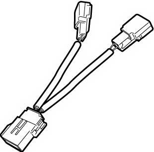
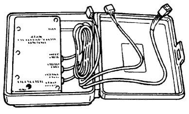
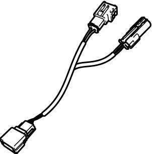
•Connect “BASE OF COLUMN” harness (1) of special tool (B) and special tool (C) to “G347” connector. With cruise control system:
•Connect “BASE OF COLUMN” harness of special tool (B) and special tool (A) to “G374” connector.
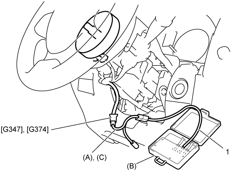
5)Set ignition “ON”.
6)Check for DTC.
Is DTC B1060-1B detected?
|
Go to Step 3.
|
Go to Step 5.
|
| 3 |
Driver air bag (inflator) module circuit check
1)Set ignition “OFF”.
2)Check for proper connection to “L04” connector.
3)Disconnect “L04” connector.
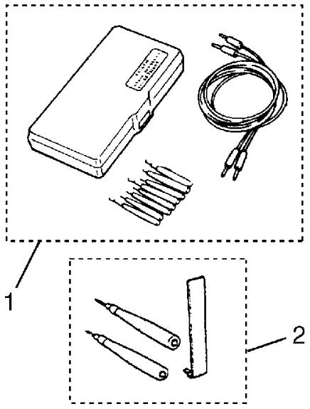
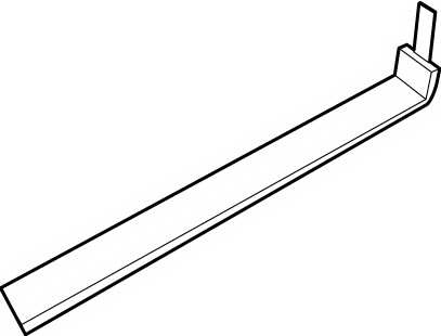
4)Release shorting bar in SDM connector inserting release tool (B).
5)Check the following points.
•Resistance between “L04-13” and “G347-2” or “G374-1” terminals: 1 Ω or less
•Resistance between “L04-14” and “G347-1” or “G374-2” terminals: 1 Ω or less 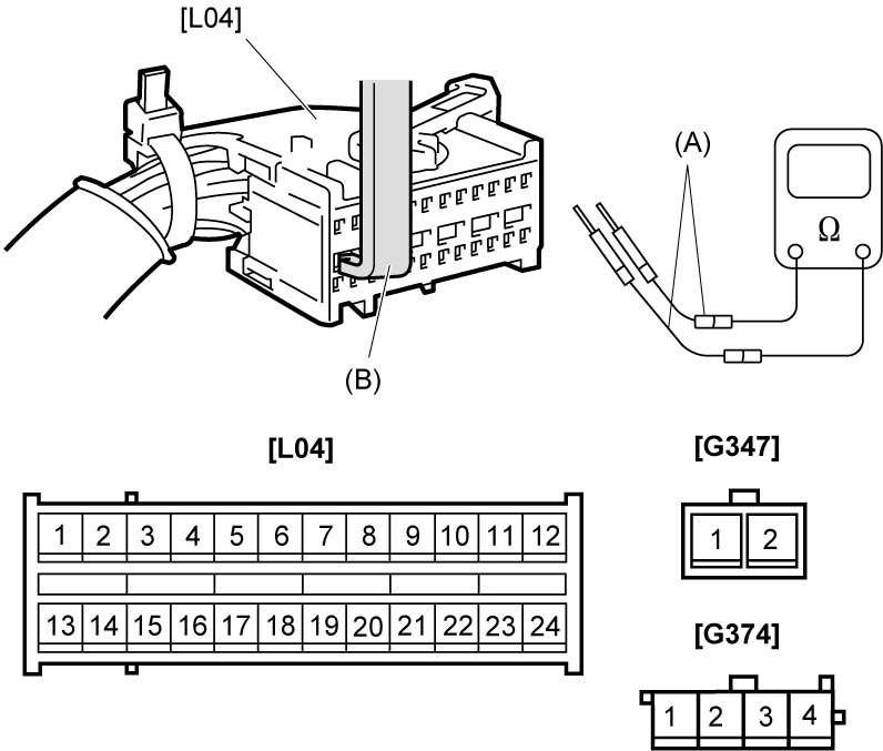 Is check result OK?
|
Replace SDM and recheck DTC.
|
Go to Step 4.
|
| 4 |
Instrument panel harness circuit check
1)Check for proper connection to “G344” connector.
2)Disconnect “G344” connector.
3)Check the following point.
•Resistance of “A1” and “A2” circuits: 1 Ω or less
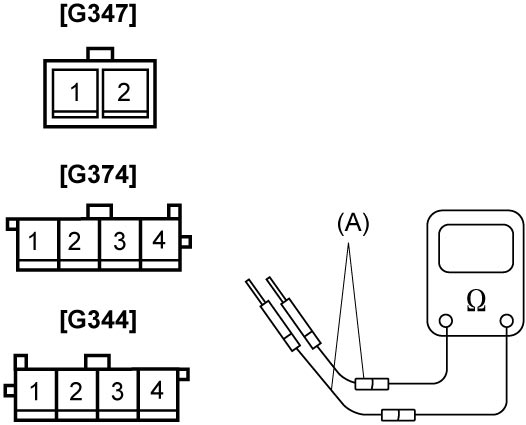 Is check result OK?
|
Replace floor harness.
|
Replace instrument panel harness.
|
| 5 |
Contact coil circuit check
1)Check contact coil circuit.
Is contact coil circuit in good condition?
|
Replace driver air bag (inflator) module.
|
Replace contact coil assembly.
|
NOTE:
Upon completion of inspection and repair work, perform the following items.
•Reconnect all air bag system components and check that all components are properly mounted.
•Clear DTCs, referring to DTC Clearance if any DTC is detected.
•Repeat Air Bag Diagnostic System Check to check that the trouble has been solved.
•Clear DTCs, referring to DTC Clearance if any DTC is detected.
•Repeat Air Bag Diagnostic System Check to check that the trouble has been solved.