Keyless Entry System Circuit Diagram
Precautions: Precautions for Diagnosing Trouble · Precautions for Replacing Ignition Key (Ignition Switch Model) · Precautions for Transmitter Disposal (Ignition Switch Model) · Precautions for Replacing Keyless Entry Control Module (Ignition Switch Model) · Precautions for Body, Cab and Accessories · General safety (00)
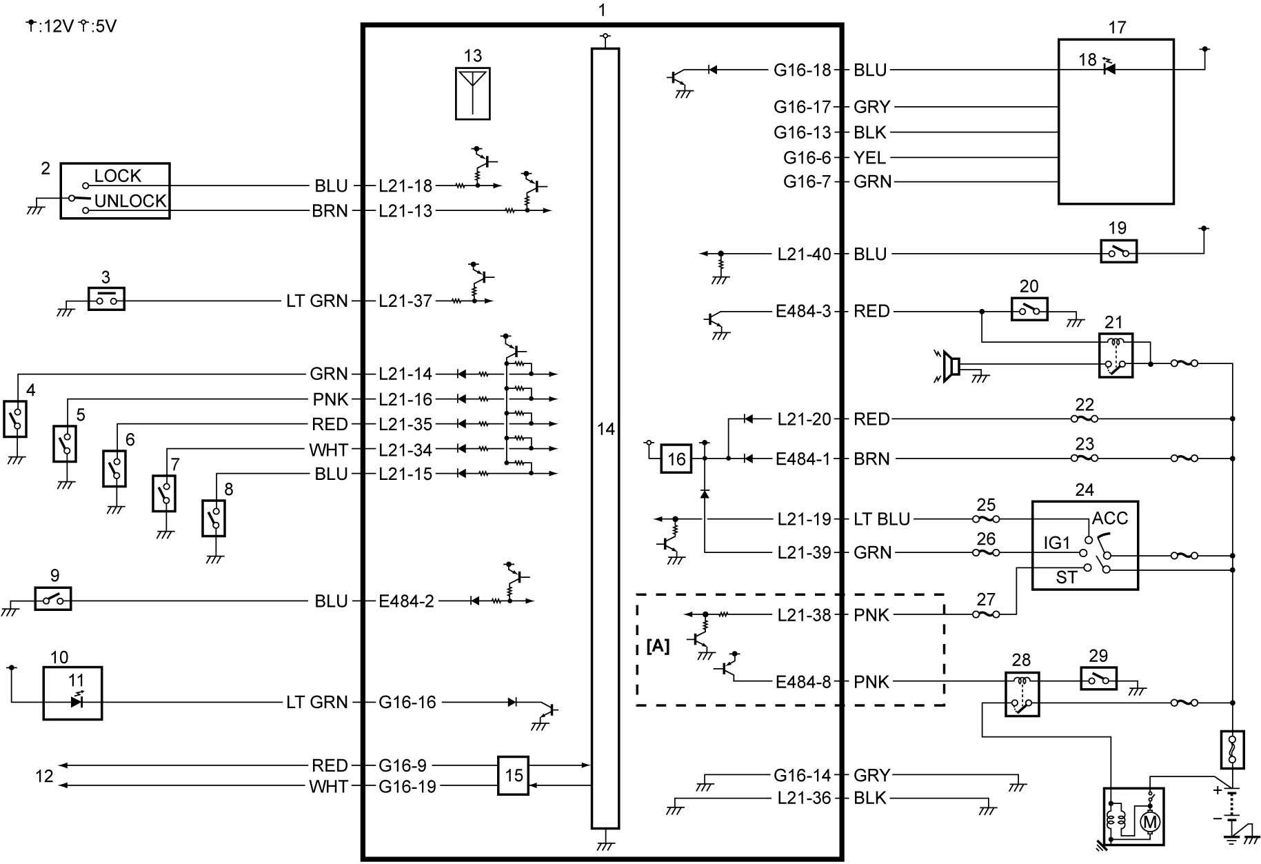
| [A]: | If equipped | 10. | Hazard warning switch | 20. | Horn switch |
| 1. | Keyless entry control module | 11. | Theft deterrent light | 21. | Horn relay |
| 2. | Door key cylinder switch | 12. | Each control module
•M16A model: CAN Communication System Circuit Diagram:M16A Model
•D16AA model: CAN Communication System Circuit Diagram:D16AA Model |
22. | “BCM” fuse |
| 3. | Rear end door opener switch | 13. | Receiver | 23. | “DOME” fuse |
| 4. | Rear end door switch | 14. | CPU | 24. | Ignition switch |
| 5. | Driver door switch | 15. | CAN driver | 25. | “ACC” fuse |
| 6. | Passenger door switch | 16. | Power supply circuit | 26. | “MTR” fuse |
| 7. | Rear door switch (L) | 17. | Immobilizer control module | 27. | “ST SIG” fuse |
| 8. | Rear door switch (R) | 18. | Ignition switch illumination | 28. | Starting motor control relay |
| 9. | Hood latch switch (if equipped) | 19. | Key reminder switch | 29. | CPP No.1 switch |