DTC P0575
Precautions: Precautions for Diagnosing Trouble · Precautions for Adaptive Cruise Control System · Precautions for Replacing RBS Control Module · General safety (00)
DTC Detecting Condition and Trouble Area
| DTC detecting condition | Trouble area |
|---|---|
|
P0575: Cruise Control Input Circuit This DTC is detected if any one of the following conditions is met.
•Signal voltage of cruise control switch signal circuit is higher than specified voltage for specified time continuously.
•ON signals of any or all of following switches of adaptive cruise control system are detected for longer than specified time.
—CRUISE (main) switch
—LIMIT switch —CANCEL switch —RES/+ switch —SET/– switch —Distance switch |
•Cruise control switch circuit / connector
•Cruise control switch •Contact coil •ECM |
Circuit Diagram
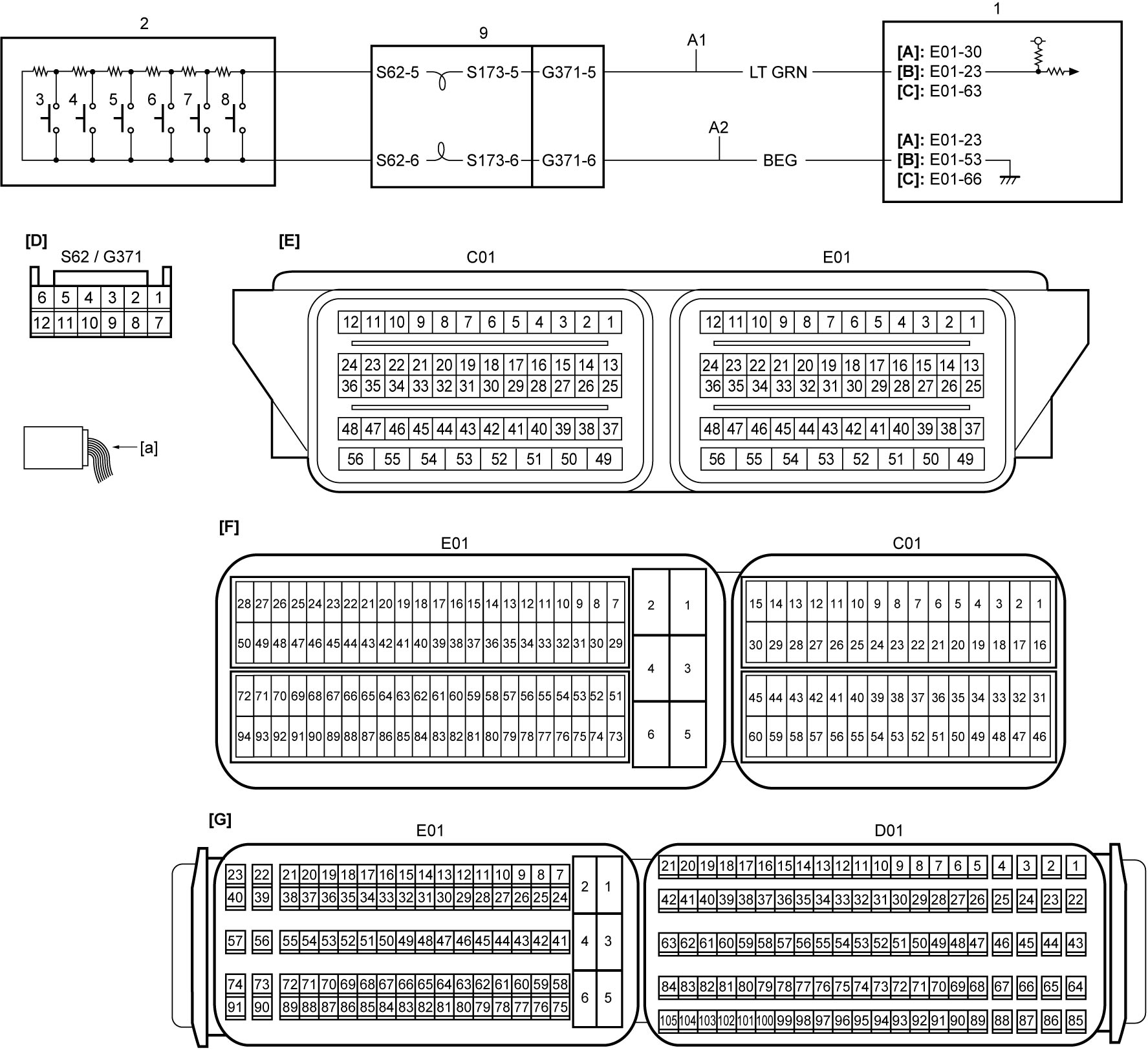
| [A]: | M16A model | [G]: | ECM connector (D16AA model) (View: [a]) | 4. | RES/+ switch |
| [B]: | K14C model | A1: | Cruise control switch signal circuit | 5. | SET/– switch |
| [C]: | D16AA model | A2: | Cruise control switch ground circuit | 6. | LIMIT switch |
| [D]: | Contact coil connector (View: [a]) | 1. | ECM | 7. | CANCEL switch |
| [E]: | ECM connector (M16A model) (View: [a]) | 2. | Cruise control switch | 8. | CRUISE (main) switch |
| [F]: | ECM connector (K14C model) (View: [a]) | 3. | Distance switch | 9. | Contact coil |
DTC Troubleshooting
| Step | Action | Yes | No |
|---|---|---|---|
| 1 |
Cruise control switch circuit check
1)Check that ignition is “OFF”.
2)Disconnect “E01” and “G371” connectors.
3)Check for proper terminal connection to “E01” and “G371” connectors.
4)If connections are OK, check the following points.
•Resistance of “A1” and “A2” circuits: less than 1 Ω
•Resistance between “A1” circuit and ground: infinity •Resistance between “A1” circuit terminal and other terminals at “G371” connector: infinity •Resistance between “A2” circuit terminal and other terminals at “G371” connector: infinity •Voltage of “A1” and “A2” circuits: approx. 0 V (When ignition is “ON”) Is check result OK?
|
Go to Step 2.
|
Repair or replace defective wire harness.
|
| 2 |
Contact coil circuit check
1)Disconnect “S62” connector.
2)Check the following points.
•Resistance between “S62-5” terminal and “S173-5” terminal of contact coil connector: less than 1 Ω
•Resistance between “S62-6” terminal and “S173-6” terminal of contact coil connector: less than 1 Ω •Resistance between “5” terminal and other terminal at “S173” connector: infinity •Resistance between “6” terminal and other terminal at “S173” connector: infinity 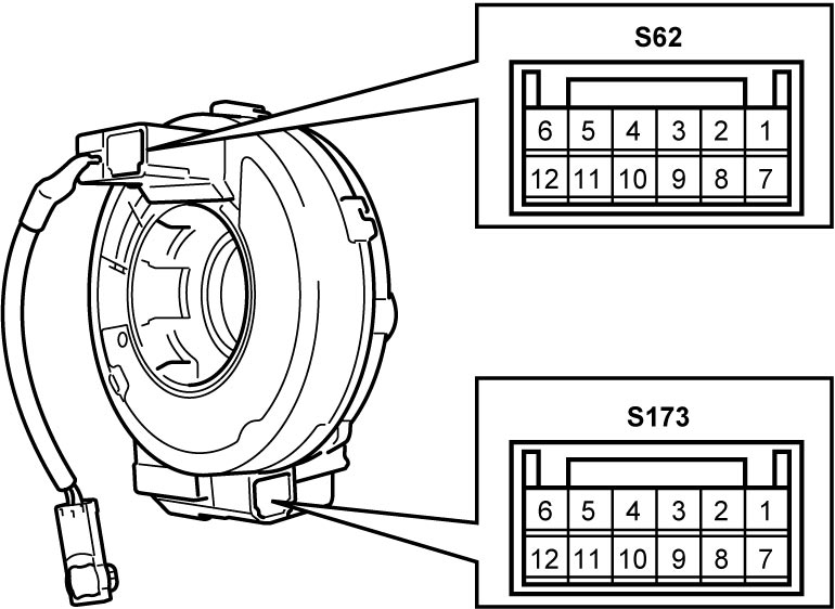 Is check result OK?
|
Go to Step 3.
|
Replace contact coil.

|
| 3 |
Cruise control switch check
1)Check cruise control switch.
Is check result OK?
|
Replace ECM and recheck DTC.
•M16A model:
•K14C model: •D16AA model: |
Replace cruise control switch.
|