DTC B1137
Precautions: Precautions for Diagnosing Trouble · Precautions for Replacing Remote Controller · Precautions for Remote Controller Disposal · Precautions for Replacing Keyless Start Control Module · Precautions for Control Systems · General safety (00)
DTC Detecting Condition and Trouble Area
| DTC detecting condition | Trouble area |
|---|---|
|
B1137: Brake Light Switch Malfunction Inconsistency between brake light switch signal and the data signal transmitted via CAN communication. |
•Brake light switch circuit / connector
•Brake light switch •Keyless start control module |
Circuit Diagram
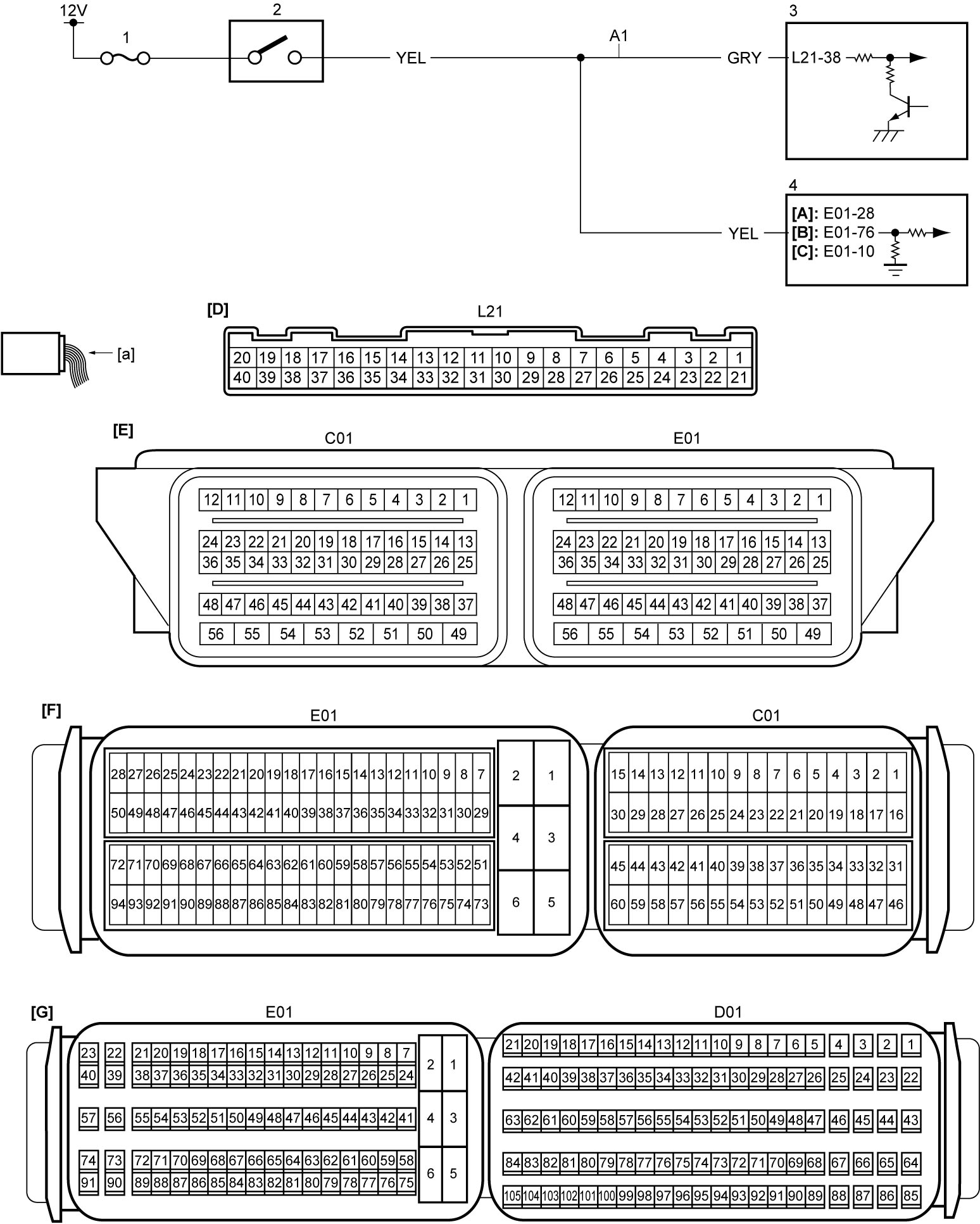
| [A]: | M16A model | [E]: | ECM connector (M16A model) (View: [a]) | 1. | “STOP” fuse |
| [B]: | K14C model | [F]: | ECM connector (K14C model) (View: [a]) | 2. | Brake light switch |
| [C]: | D16AA model | [G]: | ECM connector (D16AA model) (View: [a]) | 3. | Keyless start control module |
| [D]: | Keyless start control module connector (View: [a]) | A1: | Brake light switch signal circuit | 4. | ECM |
DTC Confirmation Procedure
1)Set ignition “ON”.
2)Depress brake pedal fully for 3 seconds or more.
3)Release brake pedal.
DTC Troubleshooting
| Step | Action | Yes | No |
|---|---|---|---|
| 1 |
DTC check
1)Check DTC in ECM.
•M16A model:
 •K14C model: •D16AA model: Is DTC P0504 detected?
|
Go to troubleshooting for applicable DTC.
|
Go to Step 2.
|
| 2 |
Brake light switch signal circuit check
1)Set ignition “OFF”.
2)Disconnect brake light switch, “E01” and “L21” connectors.
3)Check for proper terminal connection to brake light switch, “E01” and “L21” connectors.
4)If connections are OK, check that resistance of “A1” circuit is less than 1 Ω.
Is check result OK?
|
Replace keyless start control module and recheck DTC.
|
Repair or replace defective wire harness.
|