ENG A-STOP System Electric Circuit Diagram
Precautions: Precautions for Diagnosing Trouble · Precautions for Servicing ENG A-STOP System · Precautions for Replacing ENG A-STOP Control Module · Precautions for Control Systems · General safety (00)
M/T model / Twin clutch system model
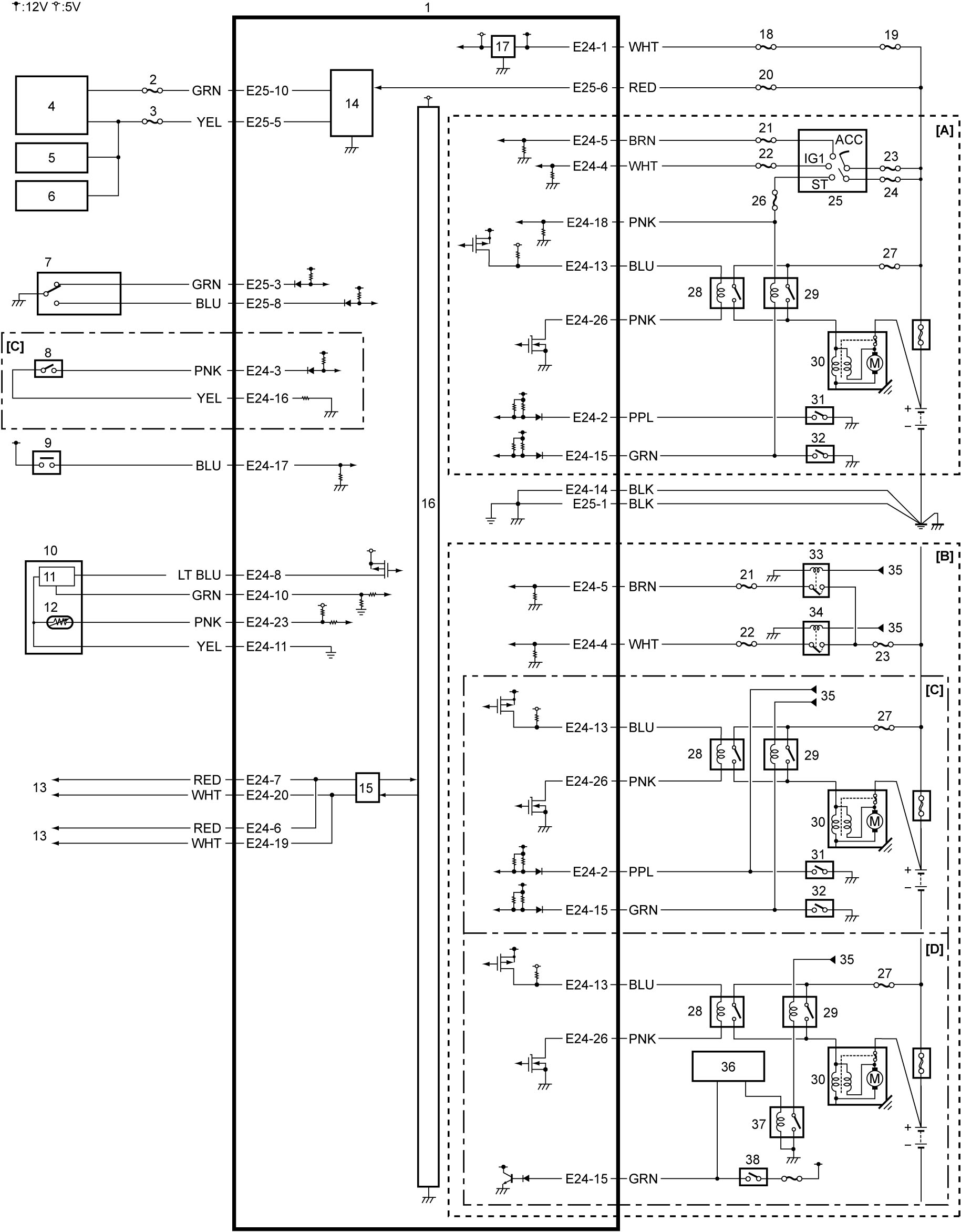
| [A]: | Ignition switch model | 11. | Electric load current sensor | 25. | Ignition switch |
| [B]: | Keyless push start model | 12. | Battery temperature sensor | 26. | “ST SIG” fuse |
| [C]: | M/T model | 13. | Each control module
•M16A model: CAN Communication System Circuit Diagram:M16A Model
•K14C model: CAN Communication System Circuit Diagram:K14C Model •D16AA model: CAN Communication System Circuit Diagram:D16AA Model |
27. | “ST” fuse |
| [D]: | Twin clutch system model | 14. | DC/DC circuit | 28. | ST2 relay |
| 1. | ENG A-STOP control module | 15. | CAN driver | 29. | Starting motor control relay |
| 2. | “ACC3” fuse | 16. | CPU | 30. | Starting motor |
| 3. | “RADIO2” fuse | 17. | Voltage regulator | 31. | CPP No.2 switch |
| 4. | Audio unit / navigation (if equipped) | 18. | “A-STOP” fuse | 32. | CPP No.1 switch |
| 5. | Combination meter | 19. | “BTRY” fuse (D16AA model) | 33. | ACC relay |
| 6. | Auto A/C panel (auto A/C model) | 20. | “DCDC” fuse | 34. | IG1 relay |
| 7. | Hood latch switch | 21. | “ACC” fuse | 35. | Keyless start control module |
| 8. | Neutral position switch | 22. | “IG1 SIG” fuse | 36. | TCM |
| 9. | ENG A-STOP OFF switch | 23. | “IGN” fuse | 37. | ST3 relay |
| 10. | Electric load current sensor & battery temperature sensor | 24. | “IGN2” fuse (D16AA model) | 38. | Brake light switch |
A/T model
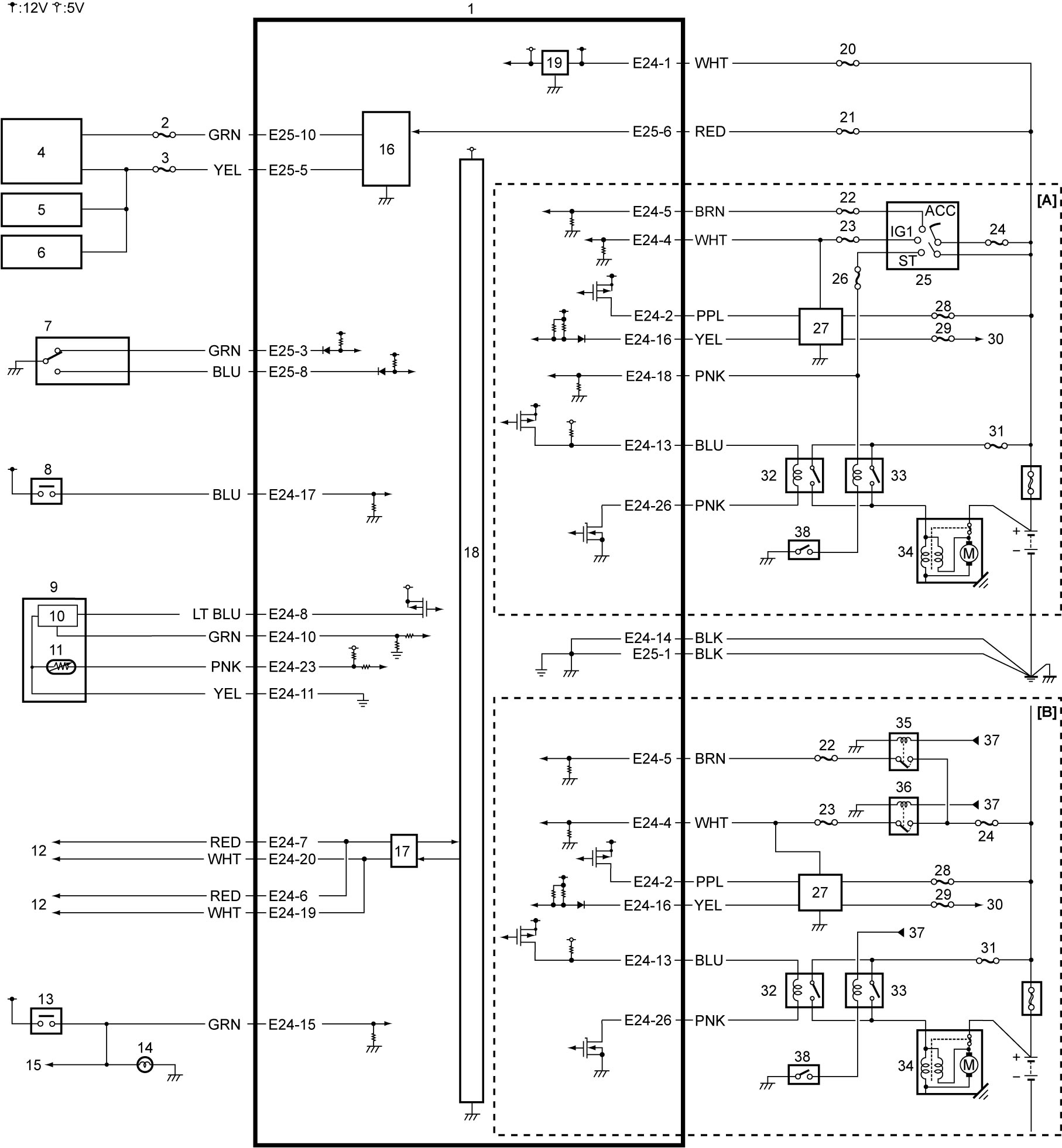
| [A]: | Ignition switch model | 13. | Brake light switch | 27. | DC/DC converter |
| [B]: | Keyless push start model | 14. | Brake light | 28. | “DCDC2” fuse |
| 1. | ENG A-STOP control module | 15. | To other control module | 29. | “T/M5” fuse |
| 2. | “ACC3” fuse | 16. | DC/DC circuit | 30. | To TCM |
| 3. | “RADIO2” fuse | 17. | CAN driver | 31. | “ST” fuse |
| 4. | Audio unit / navigation (if equipped) | 18. | CPU | 32. | ST2 relay |
| 5. | Combination meter | 19. | Voltage regulator | 33. | Starting motor control relay |
| 6. | Auto A/C panel (auto A/C model) | 20. | “A-STOP” fuse | 34. | Starting motor |
| 7. | Hood latch switch | 21. | “DCDC” fuse | 35. | ACC relay |
| 8. | ENG A-STOP OFF switch | 22. | “ACC” fuse | 36. | IG1 relay |
| 9. | Electric load current sensor & battery temperature sensor | 23. | “IG1 SIG” fuse | 37. | Keyless start control module |
| 10. | Electric load current sensor | 24. | “IGN” fuse | 38. | Transmission range sensor |
| 11. | Battery temperature sensor | 25. | Ignition switch | ||
| 12. | Each control module
•M16A model: CAN Communication System Circuit Diagram:M16A Model
•K14C model: CAN Communication System Circuit Diagram:K14C Model |
26. | “ST SIG” fuse |
Terminal Arrangement of ENG A-STOP Control Module Connector
NOTE:
For circuit name and terminal voltage, refer to Inspection of ENG A-STOP Control Module and Its Circuits.

| [A]: | ENG A-STOP control module connector (View: [a]) |