Inspection of RBS Control Module and Its Circuits
Precautions: Precautions for Diagnosing Trouble · Precautions for RBS System · Precautions for Servicing RBS System · Precautions for Removing / Installing and Replacing RBS Control Module · Precautions for Control Systems · General safety (00)
Voltage and Signal Check
1)Connect service wires (3) between RBS control module (1) and connector (2).
2)Check voltage and/or pulse signal of RBS control module using voltmeter (4) and oscilloscope (5).
NOTE:
Voltage of terminal with asterisk (*) cannot be measured by voltmeter because it is pulse signal. Check it with oscilloscope if necessary.
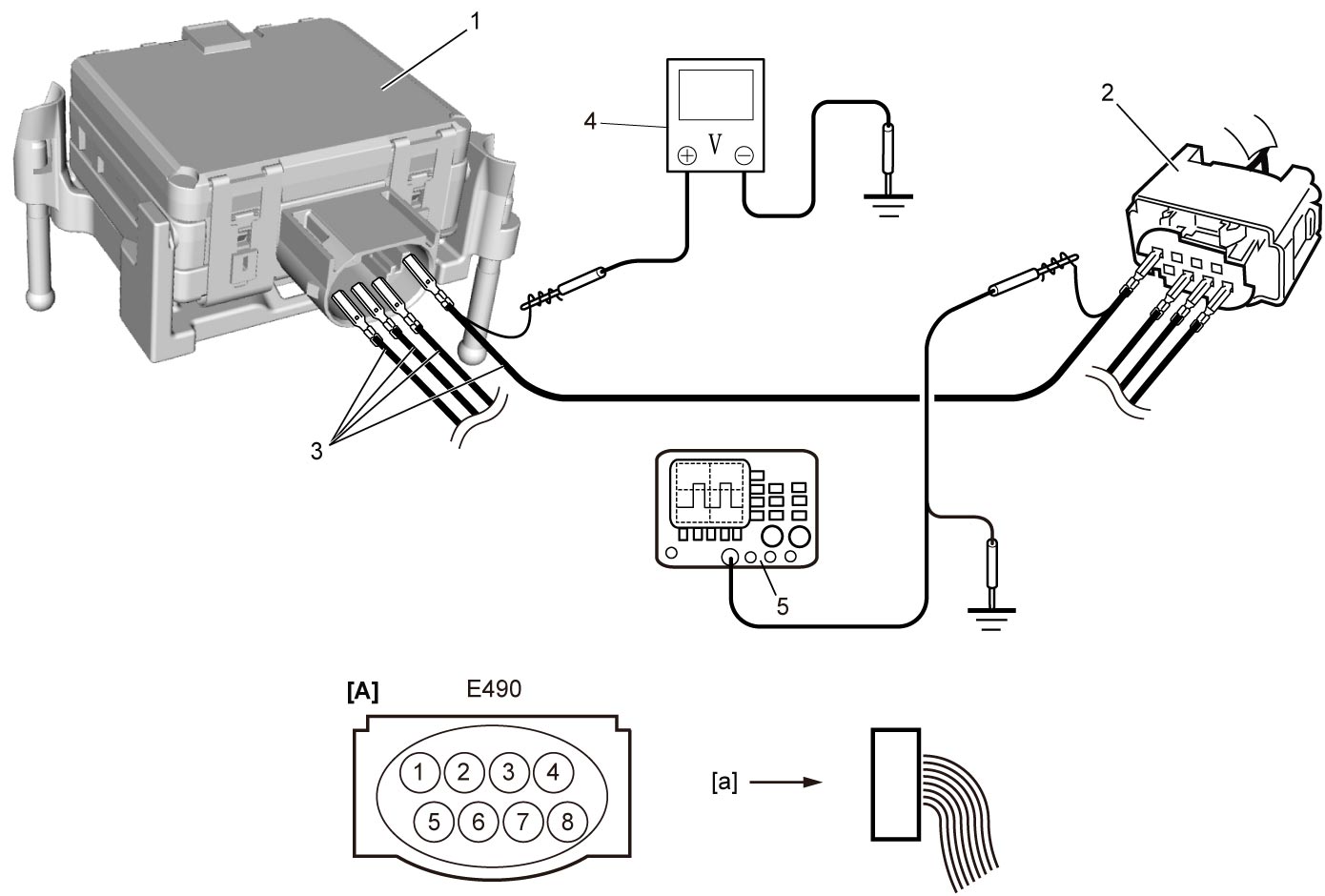
| [A]: | RBS control module connector (View: [a]) |
“E490” connector
| Terminal No. | Wire color | Circuit | Normal voltage | Condition |
|---|---|---|---|---|
| E490-1 | LT GRN | Power supply for RBS control module | 10 – 14 V | Ignition: “ON” |
| Approx. 0 V | Other than above condition | |||
| E490-2 | — | — | — | — |
| E490-3 | — | — | — | — |
| E490-4 | — | — | — | — |
| E490-5 | — | — | — | — |
| E490-6* | WHT | CAN communication line (low) | Refer to CAN communication signal. | |
| E490-7* | RED | CAN communication line (high) | ||
| E490-8 | BLK | Ground for RBS control module | Approx. 0 V | — |
Reference Waveform
Oscilloscope display
Shown below is typical waveform display provided by oscilloscope.
NOTE:
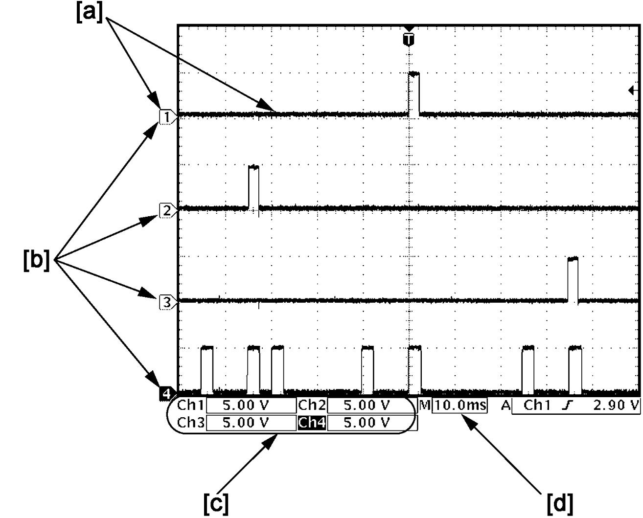

•How to read waveforms is shown below.
| [a]: | Waveform of channel 1 | [c]: | VOLT/DIV of each channel |
| [b]: | Ground level of each channel | [d]: | TIME/DIV |
•Waveform varies depending on measurement condition and vehicle spec.
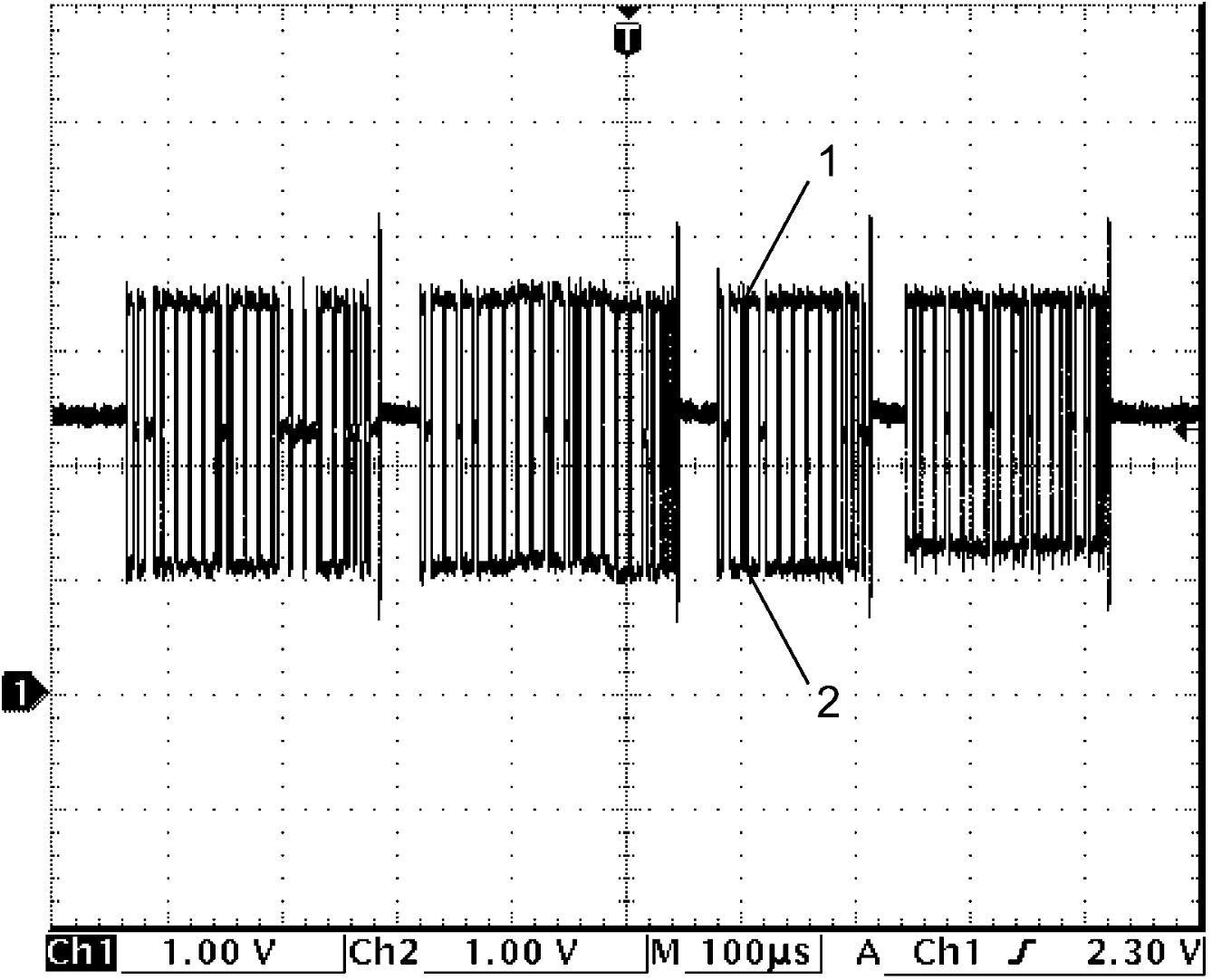
CAN communication signal
CAN communication signal (High) (1)
| Channel | Probe | Terminal No. |
|---|---|---|
| 1 | + | E490-7 |
| – | E490-8 |
CAN communication signal (Low) (2)
| Channel | Probe | Terminal No. |
|---|---|---|
| 2 | + | E490-6 |
| – | E490-8 |
Measurement condition
•Ignition: “ON”