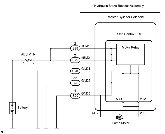
DTC C1251/51 Open in Pump Motor Circuit |
| DTC No. | DTC Detection Condition | Trouble Area |
| C1251/51 | Open in motor system circuit (motor input circuit) | Hydraulic brake booster pump motor circuit |
| 1.CHECK CONNECTION OF PUMP MOTOR WIRE HARNESS (MT+ / MT-) |
Using a screwdriver, remove the 2 plugs from the hydraulic brake booster assembly (Click here).
Check the tightening torque of the 2 screws which tighten the wire harness connecting the hydraulic brake booster assembly and the brake booster pump (Click here).
|
| ||||
| OK | |
 |
| 2.CHECK RESISTANCE OF PUMP MOTOR WIRE HARNESS (MT+ / MT-) |
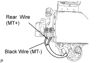 |
Using a screwdriver, remove the 2 screws and pull the wire harness from the hydraulic brake booster assembly (Click here).
Measure the resistance between the red wire (MT+) and the black wire (MT-).
|
| ||||
| OK | |
|
| 3.RECONFIRM DTC |
Reassemble the hydraulic brake booster assembly (Click here).
Install the hydraulic brake booster assembly (Click here).
Clear the DTC (Click here).
Check if the same DTC is detected (Click here).
| Condition | Proceed to |
| DTC is output | A |
| DTC is not output | B |
|
| ||||
| A | ||
 | ||
| ||
