BRAKE CONTROL / DYNAMIC CONTROL SYSTEMS VEHICLE STABILITY CONTROL SYSTEM A-TRAC Indicator Light Remains ON
DESCRIPTION
This is the A-TRAC main switch circuit. When the A-TRAC switch is turned on with the transfer in L4, the A-TRAC function is available and the A-TRAC indicator light illuminates.
WIRING DIAGRAM
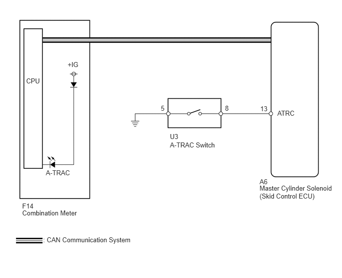
CAUTION / NOTICE / HINT
- NOTICE:
-
When replacing the master cylinder solenoid, perform calibration (See page Brake>BRAKE CONTROL / DYNAMIC CONTROL SYSTEMS>VEHICLE STABILITY CONTROL SYSTEM>CALIBRATION).
PROCEDURE
OK
NG
(See pagePower Source / Network>NETWORKING>CAN COMMUNICATION SYSTEM>HOW TO PROCEED WITH TROUBLESHOOTING)
Remove the A-TRAC switch (See page Brake>BRAKE CONTROL / DYNAMIC CONTROL SYSTEMS>TRACTION OFF SWITCH>REMOVAL).
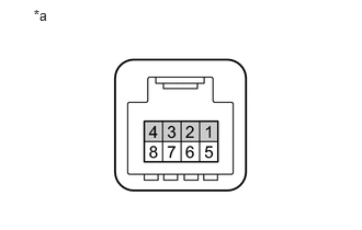
Measure the resistance according to the value(s) in the table below.
- Standard Resistance:
Tester Connection Switch Condition Specified Condition 8 - 5 Pushed in Below 1 Ω Not pushed in 10 kΩ or higher
| *a | Component without harness connected
(A-TRAC Switch) |
OK
NG
Disconnect the A6 skid control ECU connector.
Disconnect the U3 A-TRAC switch connector.
Measure the resistance according to the value(s) in the table below.
- Standard Resistance:
Tester Connection Condition Specified Condition A6-13 (ATRC) - U3-8 Always Below 1 Ω A6-13 (ATRC) - Body ground Always 10 k Ω or higher U3-5 - Body ground Always Below 1 Ω
OK
NG
Turn the ignition switch off.
Connect the intelligent tester to the DLC3.
Turn the ignition switch to ON.
Turn the intelligent tester on.
Enter the following menus: Chassis / ABS/VSC/TRC / Data List.
| Tester Display | Measurement Item/Range | Normal Condition | Diagnostic Note |
|---|---|---|---|
| A-TRAC Indicator Light | A-TRAC indicator light/ ON or OFF | ON: Indicator light on
ON: Indicator light off |
- |
Check the condition of the A-TRAC switch by operating the intelligent tester.
- OK:
The intelligent tester displays ON or OFF according to A-TRAC switch operation.
OK
(See pageVehicle Interior>METER / GAUGE / DISPLAY>METER / GAUGE SYSTEM>HOW TO PROCEED WITH TROUBLESHOOTING)
NG