PARK ASSIST / MONITORING CLEARANCE WARNING ECU INSTALLATION
CAUTION / NOTICE / HINT
- HINT:
-
A bolt without a torque specification is shown in the standard bolt chart (See page General>SPECIFICATIONS>STANDARD BOLT>SPECIFIED TORQUE FOR STANDARD BOLTS).
PROCEDURE

 89340A
1.INSTALL CLEARANCE WARNING ECU ASSEMBLY
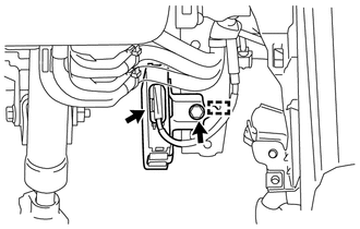
Align the positioning pins of the clearance warning ECU assembly with the body panel to temporarily install the clearance warning ECU assembly.
Install the clearance warning ECU assembly with the bolt.
Connect the connector.
55045
2.INSTALL LOWER INSTRUMENT PANEL FINISH PANEL SUB-ASSEMBLY
55474C
3.INSTALL NO. 1 INSTRUMENT CLUSTER FINISH PANEL GARNISH
62112
4.INSTALL COWL SIDE TRIM BOARD LH
67920
5.INSTALL DOOR SCUFF PLATE ASSEMBLY LH
6.CONNECT CABLE TO NEGATIVE BATTERY TERMINAL
- NOTICE:
-
When disconnecting the cable, some systems need to be initialized after the cable is reconnected (See page General>INTRODUCTION>REPAIR INSTRUCTION>INITIALIZATION).
7.CHECK SRS WARNING LIGHT