THEFT DETERRENT / KEYLESS ENTRY THEFT DETERRENT SYSTEM Horn Circuit
DESCRIPTION
When the theft deterrent system is in the alarm sounding state, the main body ECU outputs a signal repeatedly at 0.4 second intervals, causing the horns to sound.
WIRING DIAGRAM
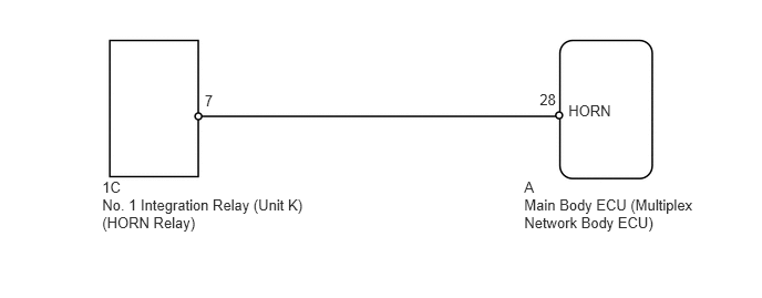
PROCEDURE
Press the horn switch and check if the horns sound.
- OK:
Horns operate normally.
OK
NG
Operate the intelligent tester according to the steps on the display and select Active Test (See page Vehicle Interior>THEFT DETERRENT / KEYLESS ENTRY>THEFT DETERRENT SYSTEM>DATA LIST / ACTIVE TEST).
| Tester Display | Test Part | Control Range | Diagnostic Note |
|---|---|---|---|
| Vehicle Horn | Vehicle horns | ON/OFF | - |
- OK:
Horns operate normally.
OK
(See pageVehicle Interior>THEFT DETERRENT / KEYLESS ENTRY>THEFT DETERRENT SYSTEM>PROBLEM SYMPTOMS TABLE)
NG
Disconnect the 1C relay connector.
Remove the main body ECU (See page Power Source / Network>POWER DISTRIBUTION>MAIN BODY ECU>REMOVAL).
Measure the resistance according to the value(s) in the table below.
- Standard Resistance:
Tester Connection Condition Specified Condition 1C-7 - A-28 (HORN) Always Below 1 Ω 1C-7 or A-28 (HORN) - Body ground Always 10 kΩ or higher
OK
NG