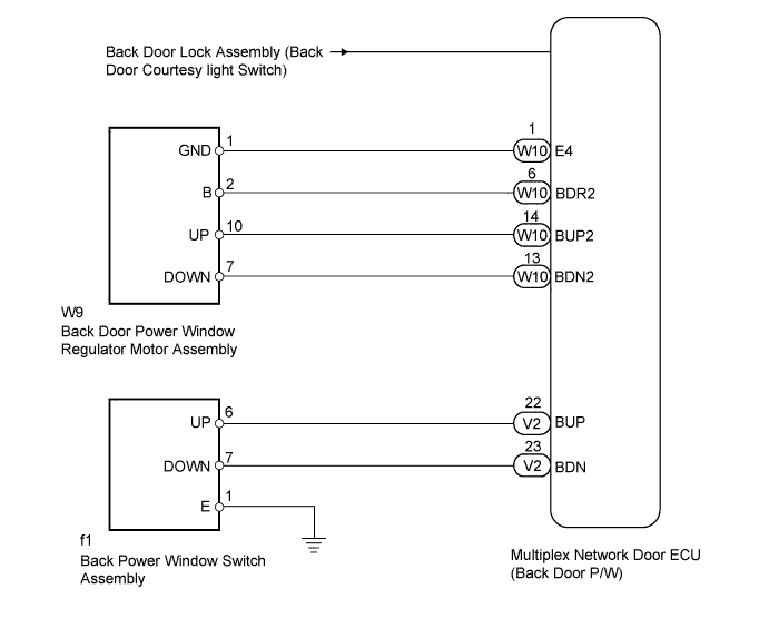
POWER WINDOW CONTROL SYSTEM > Manual Up / Down Function does not Operate on Back Door Only |
| 1.SYSTEM CHECK |
Check the back door switch.
| Result | Proceed to |
| All back door switches do not operate | A |
| Back door power window regulator switch does not operate | B |
| Tail gate control switch does not operate | C |
| Back door control switch does not operate | D |
|
| ||||
|
| ||||
|
| ||||
| A | |
 |
| 2.CHECK LIGHTING SYSTEM (BACK DOOR COURTESY LIGHT SWITCH) |
Use the Data List to check if the back door courtesy light switch is functioning properly (Click here).
| Tester Display | Measurement Item/Range | Normal Condition | Diagnostic Note |
| Back Door Courtesy Switch | Back door courtesy light switch signal / ON or OFF | ON: Back door open OFF: Back door closed | - |
|
| ||||
| OK | |
|
| 3.CHECK REAR WIPER SYSTEM (REAR WIPER POSITION) |
Use the Data List to check if the rear wiper is functioning properly (Click here).
| Tester Display | Measurement Item/Range | Normal Condition | Diagnostic Note |
| Wiper Retracted Position | Rear wiper reverse position switch signal / ON or OFF | ON: Rear wiper reverse position switch is in ON position OFF: Rear wiper reverse position switch is in OFF position | - |
| Wiper Reverse Position | Rear wiper reverse position switch signal / ON or OFF | ON: Rear wiper in reverse position OFF: Rear wiper in other position | - |
|
| ||||
| OK | |
|
| 4.CHECK FOR DTC (B2312) |
Check if DTC B2312 is output (Click here).
|
| ||||
| OK | |
|
| 5.PERFORM ACTIVE TEST USING TECHSTREAM (BACK DOOR POWER WINDOW) |
Select the Active Test, use the Techstream to generate a control command, and then check that the door window regulator operates (Click here).
| Tester Display | Test Part | Control Range | Diagnostic Note |
| Back Door power Window | Back door power window | OFF/UP/DOWN | - |
|
| ||||
| OK | ||
 | ||
| ||
| 6.INSPECT BACK DOOR POWER WINDOW REGULATOR MOTOR ASSEMBLY |
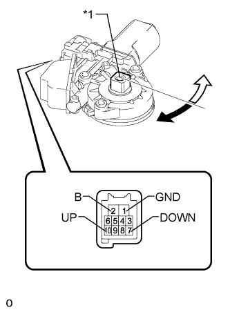 |
Remove the back door power window regulator motor (Click here).
Check that the back door power window regulator motor moves smoothly as follows.
| Measurement Condition | Specified Condition |
| Motor gear rotates clockwise (Up) |
| Motor gear rotates counterclockwise (Down) |
| *1 | Motor Gear |
 | Clockwise |
 | Counterclockwise |
|
| ||||
| OK | |
|
| 7.CHECK HARNESS AND CONNECTOR (BACK DOOR POWER WINDOW REGULATOR MOTOR ASSEMBLY - MULTIPLEX NETWORK DOOR ECU) |
Disconnect the W9 back door power window regulator motor connector.
Disconnect the W10 multiplex network door ECU connector.
Measure the resistance according to the value(s) in the table below.
| Tester Connection | Condition | Specified Condition |
| W9-10 (UP) - W10-14 (BUP2) | Always | Below 1 Ω |
| W9-7 (DOWN) - W10-13 (BDN2) | Always | Below 1 Ω |
| W9-10 (UP) - Body ground | Always | 10 kΩ or higher |
| W9-7 (DOWN) - Body ground | Always | 10 kΩ or higher |
|
| ||||
| OK | ||
| ||
| ||
| 8.INSPECT BACK DOOR POWER WINDOW REGULATOR SWITCH ASSEMBLY |
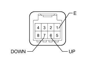 |
Remove the back door power window regulator switch (Click here).
Measure the resistance according to the value(s) in the table below.
| Tester Connection | Switch Condition | Specified Condition |
| 6 (UP) - 1 (E) | Manual up operation | Below 1 Ω |
| 7 (DOWN) - 1 (E) | Manual down operation | Below 1 Ω |
| 6 (UP) - 1 (E) | Not operated | 10 kΩ or higher |
| 7 (DOWN) - 1 (E) | Not operated | 10 kΩ or higher |
|
| ||||
| OK | |
|
| 9.CHECK HARNESS AND CONNECTOR (BACK DOOR POWER WINDOW REGULATOR SWITCH ASSEMBLY - MULTIPLEX NETWORK DOOR ECU) |
Disconnect the f1 back door power window regulator switch connector.
Disconnect the V2 multiplex network door ECU connector.
Measure the resistance according to the value(s) in the table below.
| Tester Connection | Condition | Specified Condition |
| f1-6 (UP) - V2-22 (BUP) | Always | Below 1 Ω |
| f1-7 (DOWN) - V2-23 (BDN) | Always | Below 1 Ω |
| f1-1 (E) - Body ground | Always | Below 1 Ω |
| f1-6 (UP) - Body ground | Always | 10 kΩ or higher |
| f1-7 (DOWN) - Body ground | Always | 10 kΩ or higher |
|
| ||||
| OK | ||
| ||
| ||

