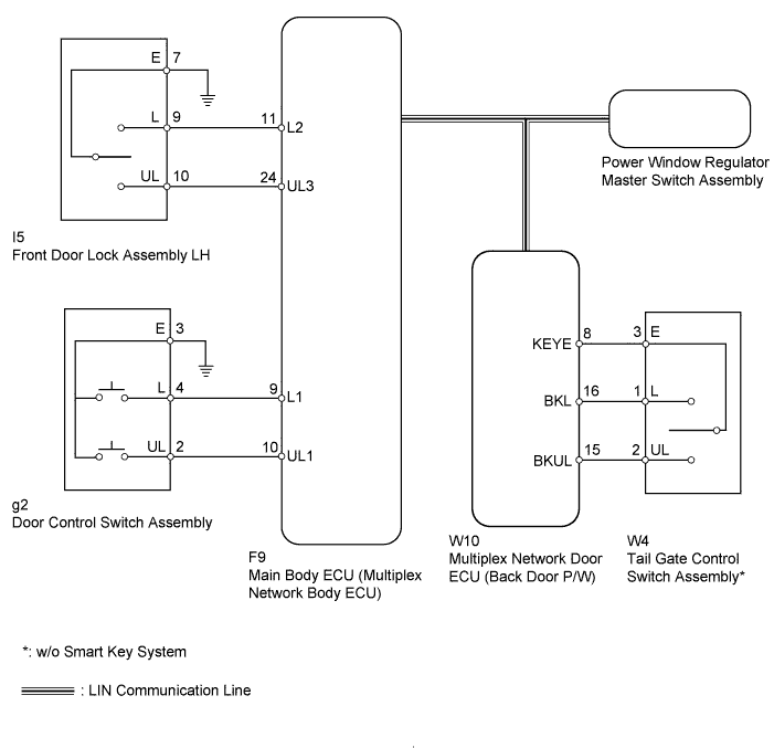
POWER DOOR LOCK CONTROL SYSTEM > All Doors LOCK/UNLOCK Functions do not Operate Via Master Switch, Driver Side Door Key Cylinder |
| 1.CHECK DOOR LOCK OPERATION |
Check the door lock operation.
| Result | Proceed to |
| No doors can be locked using multiplex network master switch | A |
| No doors can be locked using door control switch | B |
| No doors can be locked using key-linked switch | C |
| No doors can be locked using tail gate control switch* | D |
|
| ||||
|
| ||||
|
| ||||
| A | ||
 | ||
| ||
| 2.READ VALUE USING TECHSTREAM (DOOR CONTROL SWITCH) |
Use the Data List to check if the door control switch is functioning properly (Click here).
| Tester Display | Measurement Item/Range | Normal Condition | Diagnostic Note |
| Door Lock SW-Lock | Door control switch lock signal / ON or OFF | ON: Lock side of door control switch pushed OFF: Lock side of door control switch not pushed | - |
| Door Lock SW-Unlock | Door control switch unlock signal / ON or OFF | ON: Unlock side of door control switch pushed OFF: Unlock side of door control switch not pushed | - |
|
| ||||
| OK | ||
| ||
| ||
| 3.INSPECT DOOR CONTROL SWITCH ASSEMBLY |
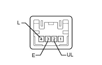 |
Remove the door control switch (Click here).
Measure the resistance according to the value(s) in the table below.
| Tester Connection | Condition | Specified Condition |
| 4 (L) - 3 (E) | Lock | Below 1 Ω |
| 4 (L) - 3 (E) | Off | 10 kΩ or higher |
| 2 (UL) - 3 (E) | Unlock | Below 1 Ω |
| 2 (UL) - 3 (E) | Off | 10 kΩ or higher |
|
| ||||
| OK | |
 |
| 4.CHECK HARNESS AND CONNECTOR (DOOR CONTROL SWITCH ASSEMBLY - MAIN BODY ECU) |
Disconnect the g2 door control switch connector.
Disconnect the F9 main body ECU connector.
Measure the resistance according to the value(s) in the table below.
| Tester Connection | Condition | Specified Condition |
| g2-2 (UL) - F9-10 (UL1) | Always | Below 1 Ω |
| g2-4 (L) - F9-9 (L1) | Always | Below 1 Ω |
| g2-3 (E) - Body ground | Always | Below 1 Ω |
| g2-2 (UL) - Body ground | Always | 10 kΩ or higher |
| g2-4 (L) - Body ground | Always | 10 kΩ or higher |
|
| ||||
| OK | ||
| ||
| ||
| 5.READ VALUE USING TECHSTREAM (KEY-LINKED SWITCH) |
Use the Data List to check if the door key-linked switch is functioning properly (Click here).
| Tester Display | Measurement Item/Range | Normal Condition | Diagnostic Note |
| Door Key SW-Lock | Driver side door key-linked switch lock signal / ON or OFF | ON: Driver side door key cylinder turned to lock position OFF: Driver side door key cylinder not turned to lock position | - |
| D Door Key SW-UL | Driver side door key-linked switch unlock signal / ON or OFF | ON: Driver side door key cylinder turned to unlock position OFF: Driver side door key cylinder not turned to unlock position | - |
|
| ||||
| OK | ||
| ||
| ||
| 6.INSPECT FRONT DOOR LOCK ASSEMBLY LH (KEY-LINKED SWITCH) |
Remove the front door lock LH (Click here).
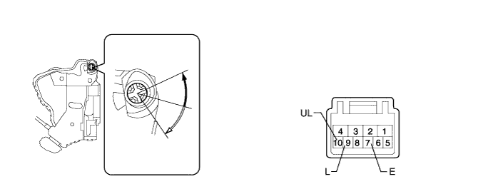
 | Lock |  | Unlock |
Measure the resistance according to the value(s) in the table below.
| Tester Connection | Condition | Specified Condition |
| 9 (L) - 7 (E) | Lock | Below 1 Ω |
| 9 (L) - 7 (E) | Off | 10 kΩ or higher |
| 10 (UL) - 7 (E) | Unlock | Below 1 Ω |
| 10 (UL) - 7 (E) | Off | 10 kΩ or higher |
|
| ||||
| OK | |
|
| 7.CHECK HARNESS AND CONNECTOR (FRONT DOOR LOCK ASSEMBLY LH - MAIN BODY ECU AND BODY GROUND) |
Disconnect the I5 door lock connector.
Remove the main body ECU connector. (Click here)
Measure the resistance according to the value(s) in the table below.
| Tester Connection | Condition | Specified Condition |
| I5-10 (UL) - F9-24 (UL3) | Always | Below 1 Ω |
| I5-9 (L) - F9-11 (L2) | Always | Below 1 Ω |
| I5-7 (E) - Body ground | Always | Below 1 Ω |
| I5-10 (UL) - Body ground | Always | 10 kΩ or higher |
| I5-9 (L) - Body ground | Always | 10 kΩ or higher |
|
| ||||
| OK | ||
| ||
| ||
| 8.READ VALUE USING TECHSTREAM (TAIL GATE CONTROL SWITCH) |
Use the Data List to check if the tail gate control switch and back door are functioning properly (Click here).
| Tester Display | Measurement Item/Range | Normal Condition | Diagnostic Note |
| Key Switch Operation Locked | Tail gate control switch signal / ON or OFF | ON: Back door key cylinder turned to lock position OFF: Back door key cylinder not turned | - |
| Key Switch Operation Unlocked | Tail gate control switch signal / ON or OFF | ON: Back door key cylinder turned to unlock position OFF: Back door key cylinder not turned | - |
| Back Door Courtesy Switch | Back door courtesy switch signal / ON or OFF | ON: Back door open OFF: Back door closed | - |
| Result | Proceed to |
| OK | A |
| NG (Key Switch Operation Locked or Key Switch Operation Unlocked) | B |
| NG (Back Door Courtesy Switch) | C |
|
| ||||
|
| ||||
| A | ||
| ||
| ||
| 9.INSPECT TAIL GATE CONTROL SWITCH ASSEMBLY |
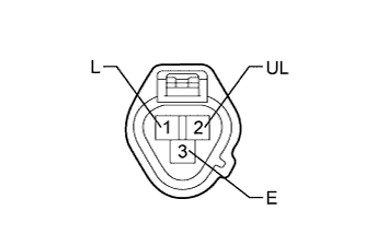 |
Remove the tail gate control switch (Click here).
Measure the resistance according to the value(s) in the table below.
| Tester Connection | Condition | Specified Condition |
| 1 (L) - 3 (E) | Lock position | Below 1 Ω |
| 1 (L) - 3 (E) | Unlock position | 10 kΩ or higher |
| 2 (UL) - 3 (E) | Unlock position | Below 1 Ω |
| 2 (UL) - 3 (E) | Lock position | 10 kΩ or higher |
|
| ||||
| OK | |
|
| 10.CHECK HARNESS AND CONNECTOR (TAIL GATE CONTROL SWITCH ASSEMBLY - MULTIPLEX NETWORK DOOR ECU) |
Disconnect the W4 tail gate control switch connector.
Disconnect the W10 multiplex network door ECU connector.
Measure the resistance according to the value(s) in the table below.
| Tester Connection | Condition | Specified Condition |
| W4-1 (L) - W10-16 (BKL) | Always | Below 1 Ω |
| W4-2 (UL) - W10-15 (BKUL) | Always | Below 1 Ω |
| W4-3 (E) - W10-8 (KEYE) | Always | Below 1 Ω |
| W4-1 (L) - Body ground | Always | 10 kΩ or higher |
| W4-2 (UL) - Body ground | Always | 10 kΩ or higher |
|
| ||||
| OK | ||
| ||
| ||

