ENGINE ASSEMBLY > REMOVAL |
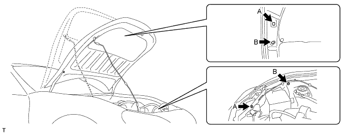
| 1. SET HOOD SUB-ASSEMBLY |
Change the front hood stay position from A to B, and support the hood sub-assembly at position B.
| 2. RECOVER REFRIGERANT FROM REFRIGERATION SYSTEM (w/ Air Conditioning System) |
for HFC-134a (R134a):
(Click here)
for HFO-1234yf (R1234yf):
(Click here)
| 3. DISCHARGE FUEL SYSTEM PRESSURE |
| 4. DISCONNECT CABLE FROM NEGATIVE BATTERY TERMINAL |
| 5. REMOVE FRONT SUSPENSION UPPER TO COWL BRACE SUB-ASSEMBLY LH |
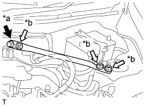 |
Remove the bolt, 3 nuts and the front suspension upper to cowl brace sub-assembly LH
| *a | Bolt |
| *b | Nut |
| 6. REMOVE FRONT SUSPENSION UPPER TO COWL BRACE SUB-ASSEMBLY RH |
| 7. REMOVE AIR CLEANER CAP WITH AIR CLEANER HOSE |
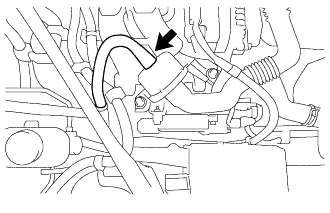 |
Disconnect the hose.
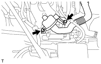 |
Remove the 2 bolts and disconnect the chamber.
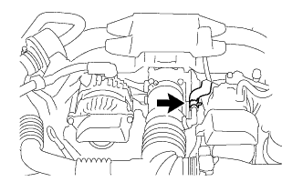 |
Loosen the hose clamp and disconnect the No. 2 ventilation hose.
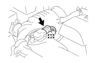 |
Disconnect the mass air flow meter connector.
Disengage the clamp and separate the wire harness from the air cleaner cap.
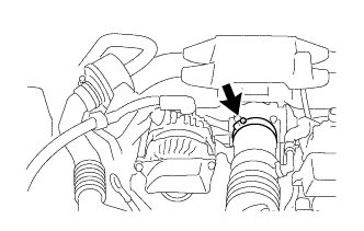 |
Loosen the hose clamp.
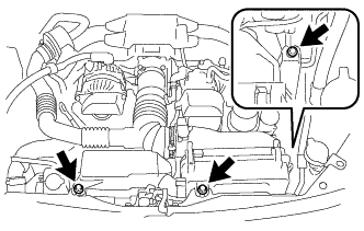 |
Remove the 3 bolts and air cleaner cap with air cleaner hose.
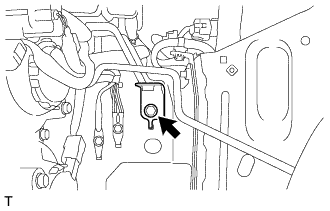 |
Remove the bolt and stay from the body.
| 8. DRAIN ENGINE OIL |
Remove the oil filler cap.
Remove the oil pan drain plug and drain the oil into a container.
Clean and install the oil pan drain plug with a new oil pan drain plug gasket.
| 9. DRAIN ENGINE COOLANT |
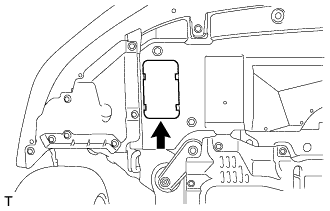 |
Remove the service hole cover from the front bumper under cover.
Connect a hose with an inside diameter of 8 mm (0.315 in.) to the drain plug.
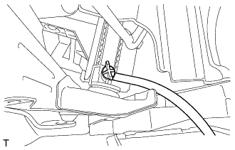 |
Loosen the radiator drain cock plug.
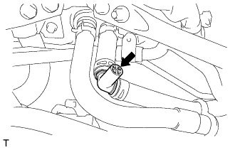 |
Open the air bleed plug on the heater hose side. (for LHD)
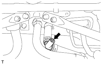 |
Open the air bleed plug on the heater hose side. (for RHD)
Remove the radiator cap and drain the coolant.
| 10. REMOVE RADIATOR RESERVE TANK ASSEMBLY |
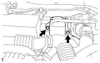 |
Remove the 2 bolts and radiator reserve tank assembly.
| 11. REMOVE WATER FILLER SUB-ASSEMBLY |
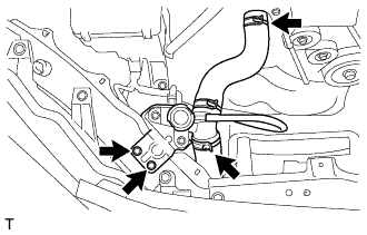 |
Remove the 2 bolts and disconnect the water filler sub-assembly.
Remove the 2 clamps and water filler sub-assembly.
| 12. REMOVE INJECTOR DRIVER |
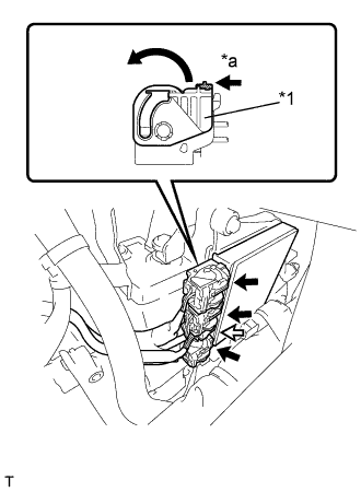 |
Move the lock levers in the direction indicated by the arrow to release the 3 connector locks. Disconnect the 4 connectors from the injector driver.
| *1 | Lock Lever |
| *a | Release |
 | Lock with Connector |
 | Normal Connector |
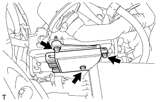 |
Remove the 3 bolts and injector driver.
| 13. DISCONNECT ENGINE WIRE (for RHD) |
for Automatic Transmission:
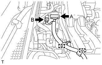 |
Release the lock of connector (A) and disconnect the connector.
Disconnect the connector (B).
Disconnect the 2 wire harness clamps.
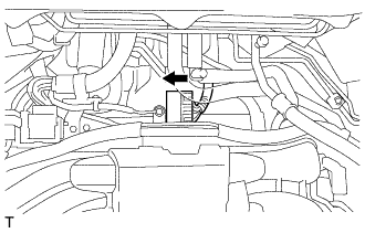 |
Slide the connector in the direction shown in the illustration, and disconnect the wire harness.
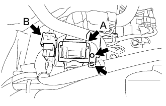 |
Remove the 2 bolts and the wire harness bracket from the No. 2 engine hanger.
Release the lock of connector (A) and disconnect the connector.
Disconnect the connector (B).
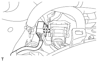 |
Disconnect the wire harness clamp and wire harness from the No. 2 engine hanger.
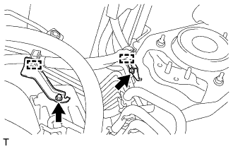 |
Disconnect the 2 wire harness clamps.
Remove the 2 bolts and 2 wire harness clamp brackets.
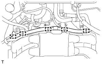 |
Disconnect the 5 wire harness clamps.
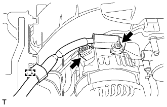 |
Disconnect the terminal cap.
Remove the nut and disconnect the wire harness from terminal B.
Disconnect the generator connector and disengage the clamp.
| 14. DISCONNECT ENGINE WIRE (for LHD) |
|
Remove the 2 bolts and the wire harness clamp bracket from the No. 2 engine hanger.
Release the lock of connector (A) and disconnect the connector.
Disconnect the connector (B).
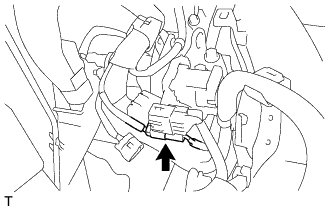 |
Disconnect the connector.
|
Disconnect the wire harness clamp and wire harness from the No. 2 engine hanger.
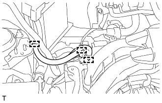 |
Disconnect the 3 wire harness clamps.
for Automatic Transmission:
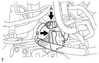 |
Release the lock of connector (A) and disconnect the connector.
Disconnect the connector (B).
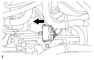 |
Slide the connector in the direction shown in the illustration, and disconnect the wire harness.
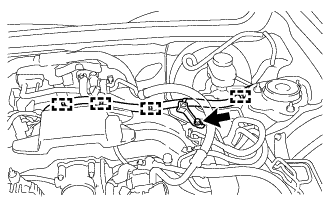 |
Disconnect the 4 wire harness clamps.
Remove the bolt and wire harness clamp bracket.
|
Disconnect the terminal cap.
Remove the nut and disconnect the wire harness from terminal B.
Disconnect the generator connector and disengage the clamp.
| 15. REMOVE NO. 1 ENGINE COVER SUB-ASSEMBLY |
| 16. DISCONNECT VACUUM TUBE CONNECTOR HOSE (for Automatic Transmission) |
for LHD:
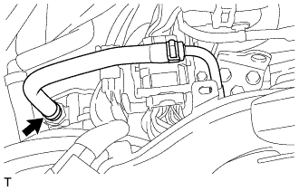 |
Loosen the hose clamp and disconnect the vacuum tube connector hose.
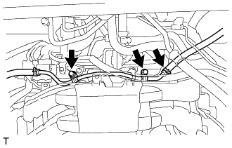 |
Remove the 2 bolts and disconnect the vacuum tube connector hose.
for RHD:
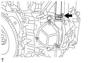 |
Loosen the hose clamp and disconnect the union to check valve hose.
| 17. DISCONNECT VACUUM TUBE CONNECTOR HOSE (for Manual Transmission) |
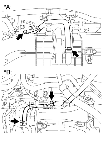 |
Loosen the hose clamp and disconnect the union to check valve hose from the intake manifold.
| *A | for LHD |
| *B | for RHD |
| 18. REMOVE EXHAUST MANIFOLD |
| 19. FIX FRONT EXHAUST PIPE SUB-ASSEMBLY (for Manual Transmission) |
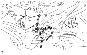 |
Tie the front exhaust pipe sub-assembly to the front cross member sub-assembly with rope.
| 20. DISCONNECT HEATER WATER HOSE |
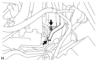 |
Loosen the 2 hose clamps and disconnect the 2 heater water hoses.
| 21. DISCONNECT NO. 1 TRANSMISSION OIL COOLER HOSE (for Automatic Transmission) |
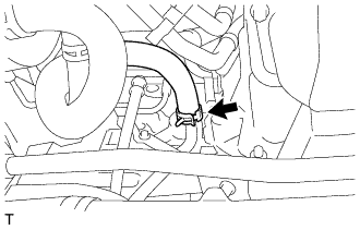 |
Loosen the clip and disconnect the No. 1 transmission oil cooler hose.
| 22. REMOVE SUCTION HOSE SUB-ASSEMBLY (w/ Air Conditioning System) |
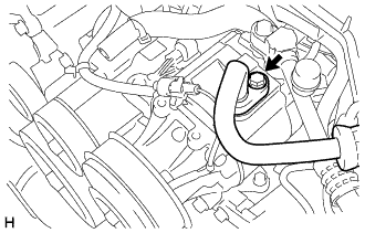 |
Remove the bolt and disconnect the suction hose sub-assembly from the compressor assembly with pulley.
Remove the O-ring from the discharge hose sub-assembly.
for LHD:
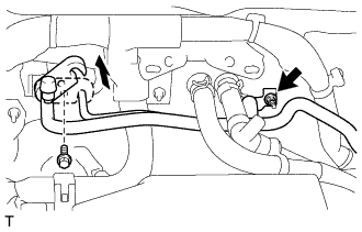 |
Remove the bolt and slide the hook connector.
Remove the nut and suction pipe sub-assembly.
Remove the O-ring from the suction pipe sub-assembly.
for RHD:
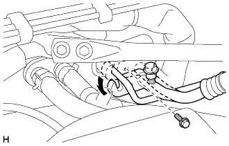 |
Remove the bolt and slide the hook connector.
Disconnect the suction pipe sub-assembly.
Remove the O-ring from the suction pipe sub-assembly.
| 23. DISCONNECT NO. 1 COOLER REFRIGERANT DISCHARGE HOSE (w/ Air Conditioning System) |
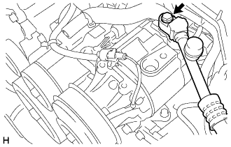 |
Remove the bolt and disconnect the No. 1 cooler refrigerant discharge hose from the compressor with magnet clutch.
Remove the O-ring from the No. 1 cooler refrigerant discharge hose.
| 24. REMOVE STARTER ASSEMBLY (for Automatic Transmission) |
| 25. REMOVE STARTER ASSEMBLY (for Manual Transmission) |
| 26. DISCONNECT NO. 3 TRANSMISSION OIL COOLER HOSE (for Automatic Transmission) |
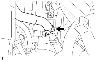 |
Loosen the clip and disconnect the No. 3 transmission oil cooler hose.
| 27. DISCONNECT RADIATOR OUTLET HOSE |
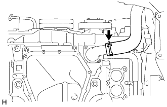 |
Loosen the clip and disconnect the radiator outlet hose.
| 28. DISCONNECT GROUNDED CABLE |
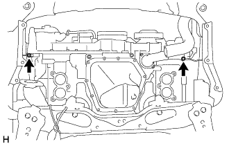 |
Remove the 2 bolts and disconnect the 2 grounded cables.
| 29. REMOVE REAR ENGINE UNDER COVER LH (w/ Floor Under Cover) |
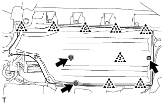 |
Remove the 3 bolts and 8 clips, then remove the rear engine under cover LH.
| 30. REMOVE FRONT STABILIZER BAR (for Automatic Transmission) |
| 31. FIX FRONT EXHAUST PIPE ASSEMBLY (for Automatic Transmission) |
|
Tie the front exhaust pipe assembly to the front cross member sub-assembly with rope.
| 32. SEPARATE AUTOMATIC TRANSMISSION ASSEMBLY (for Automatic Transmission) |
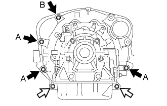 |
Remove the 3 bolts and 2 nuts.
| Bolt |
| Nut |
| 33. REMOVE MANUAL TRANSMISSION ASSEMBLY (for Manual Transmission) |
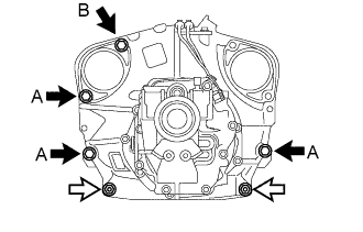 |
Remove the 3 bolts and 2 nuts.
| Bolt |
| Nut |
| 34. SEPARATE FRONT CROSS MEMBER SUB-ASSEMBLY |
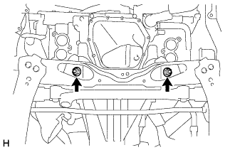 |
Remove the 2 nuts from the front cross member sub-assembly.
| 35. REMOVE FLYWHEEL HOUSING UNDER COVER |
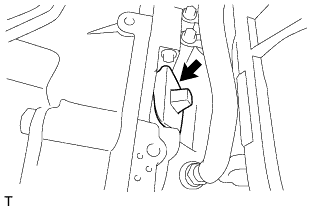 |
Remove the flywheel housing side cover from the automatic transmission assembly.
| 36. REMOVE DRIVE PLATE SETTING HEXAGON BOLT (for Automatic Transmission) |
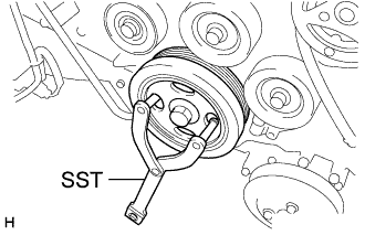 |
Using SST, hold the crankshaft pulley.
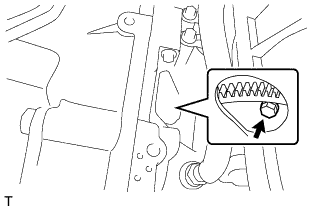 |
Remove the 6 drive plate and torque converter setting bolt.
| 37. SEPARATE FUEL HOSE |
for Clamp Type:
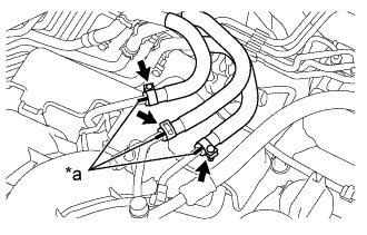 |
Put matchmarks on the fuel hoses and fuel pipes.
| *a | matchmark |
Remove the clamp and disconnect the fuel tube, No. 2 fuel tube and fuel tube from the fuel pipe.
for Metal Type:
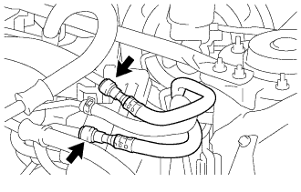 |
Using SST, disconnect the fuel tube and No. 2 fuel tube from the fuel pipe (Click here).
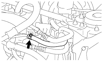 |
Remove the clamp and disconnect the No. 2 fuel vapor feed hose from the fuel pipe.
| 38. INSTALL ENGINE HANGER |
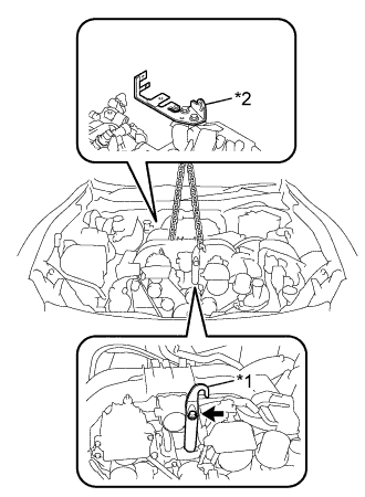 |
Install the engine hanger with the bolt, as shown in the illustration.
| *1 | No. 1 Engine Hanger |
| *2 | No. 2 Engine Hanger |
| No. 1 Engine Hanger | 12281-38030 |
| Bolt | 90119-14120 |
Use an engine sling device and a mini crane to hold the engine.
| 39. SUPPORT TRANSMISSION ASSEMBLY |
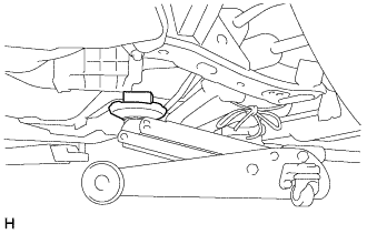 |
Support the transmission assembly clutch housing with a jack.
| 40. REMOVE ENGINE ASSEMBLY |
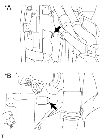 |
Remove the bolt from the transmission assembly.
| *A | for Automatic Transmission |
| *B | for Manual Transmission |
Hoist the engine assembly up with an engine sling device and a mini crane.
| 41. REMOVE DRIVE PLATE AND RING GEAR SUB-ASSEMBLY (for Automatic Transmission) |
|
Using SST, hold the crankshaft.
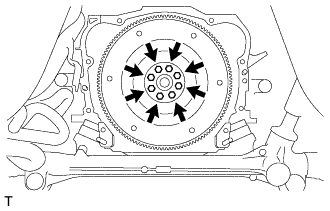 |
Remove the 8 bolts, drive plate and ring gear sub-assembly and rear drive plate spacer.
| 42. REMOVE CLUTCH COVER ASSEMBLY (for Manual Transmission) |
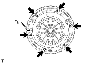 |
Put the matchmarks on the clutch cover assembly and the flywheel sub-assembly.
| *a | Matchmark |
Loosen the 6 bolts one turn at a time until spring tension is released.
Remove the 6 bolts and pull off the clutch cover assembly.
| 43. REMOVE CLUTCH DISC ASSEMBLY (for Manual Transmission) |
Remove the clutch disc assembly.
| 44. REMOVE FLYWHEEL SUB-ASSEMBLY (for Manual Transmission) |
|
Using SST, hold the crankshaft.
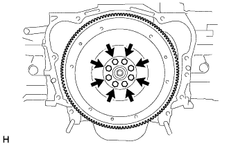 |
Remove the 8 bolts and flywheel sub-assembly.
| 45. REMOVE NO. 1 CRANKSHAFT POSITION SENSOR PLATE |
Remove the No. 1 crankshaft position sensor plate.
| 46. INSTALL ENGINE STAND |
Set the engine on an engine stand.
| 47. REMOVE FRONT ENGINE MOUNTING BRACKET |
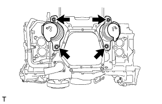 |
Remove the 4 bolts and 2 front engine mounting brackets.