 |
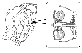
Engage the splines of the input shaft and turbine runner.
AUTOMATIC TRANSMISSION ASSEMBLY > INSTALLATION |
| 1. INSTALL TORQUE CONVERTER ASSEMBLY |
|
Engage the splines of the input shaft and turbine runner.
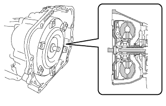 |
Engage the splines of the stator shaft and stator while turning the torque converter assembly.
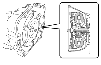 |
Turn the torque converter assembly to engage the key of the oil pump drive gear into the slot on the torque converter assembly.
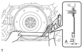 |
Using a vernier caliper and straightedge, measure dimension A between the transmission contact surface of the engine and the torque converter contact surface of the drive plate.
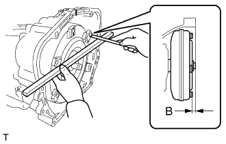 |
Using a vernier caliper and straightedge, measure dimension B shown in the illustration and check that dimension B is more than dimension A, which was measured in the first step.
| 2. INSTALL OIL COOLER TUBE |
Install the oil cooler tube with the bolt to the automatic transmission assembly.
Connect the 2 water by-pass hoses to the transmission oil cooler with the 4 hose clamps.
| 3. INSTALL WIRE HARNESS |
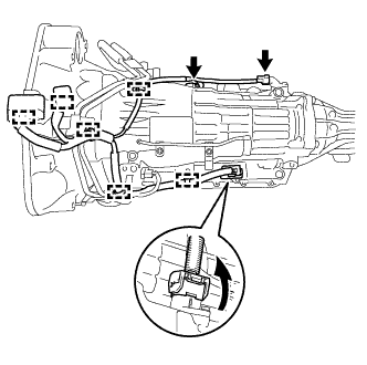 |
Install the wire harness to the automatic transmission assembly with engage the 6 wire harness clamps.
Connect the park/neutral position switch connector, transmission wire connector and the transmission revolution sensor connector.
| 4. INSTALL AUTOMATIC TRANSMISSION ASSEMBLY |
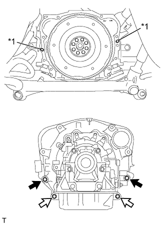 |
Confirm that 2 knock pins are on the automatic transmission assembly contact surface of the engine cylinder block before automatic transmission assembly installation.
Keeping the engine assembly and the automatic transmission assembly in a horizontal position, align the knock pins with each hole on the automatic transmission assembly and install the 2 bolts and 2nuts.
| *1 | Knock Pin |
 | Bolt |
 | Nut |
| 5. INSTALL REAR NO. 1 ENGINE MOUNTING INSULATOR |
Install the rear No. 1 engine mounting insulator to the automatic transmission assembly with the 4 bolts.
| 6. INSTALL REAR NO. 2 ENGINE MOUNTING INSULATOR |
Install the rear No. 2 engine mounting insulator to the rear No. 1 engine mounting insulator with 2 washers and 2 nuts.
Install the rear No. 2 engine mounting insulator to the body with the 4 bolts.
| 7. INSTALL EXHAUST PIPE BRACKET |
Install the exhaust pipe bracket with the 2 bolts.
| 8. INSTALL FLOOR SHIFT GEAR SHIFTING ROD SUB-ASSEMBLY |
Apply MP grease to the pin.
Install the floor shift gear shifting rod sub-assembly to the transmission control shaft lever RH with the pin and a clip.
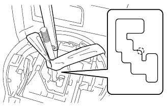
While pushing the shift lock release button, move the shift lever to N.
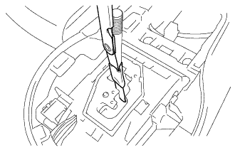 |
Using tape, hold a 0.3 mm feeler gauge on the floor shift control select lever.
 |
Using tape, attach the floor shift control select lever to the console box assembly.
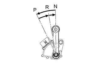 |
Turn the transmission control shaft lever RH of the park/neutral position switch assembly counterclockwise until it stops, and turn it clockwise 2 notches to set it to the N position.
Temporarily install the floor shift gear shifting rod sub-assembly with the nut.
Tighten the nut while lightly pushing the lever rearward.
| 9. INSTALL TRANSMISSION REVOLUTION SENSOR (NT) |
Coat a new O-ring with ATF and install it to the transmission revolution sensor (NT).
Install the transmission revolution sensor (NT) with the bolt.
Connect the transmission revolution sensor connector.
| 10. CONNECT OIL COOLER TUBE |
Fasten the oil cooler pipe with the oil cooler tube using 2 bolts.
| 11. INSTALL TRANSMISSION OIL COOLER HOSE |
Install the 2 transmission oil cooler hoses to the transmission oil cooler with the 4 hose clamps.
| 12. INSTALL EXHAUST MANIFOLD |
| 13. CONNECT AUTOMATIC TRANSMISSION ASSEMBLY |
Install the 2 bolts to the automatic transmission assembly.
| 14. INSTALL DRIVE PLATE AND TORQUE CONVERTER SETTING BOLT |
Install the 6 drive plate and torque converter setting bolt.
| 15. INSTALL FLYWHEEL HOUSING UNDER COVER |
Install the flywheel housing side cover.
| 16. CONNECT VACUUM TUBE CONNECTOR HOSE (for LHD) |
Connect the vacuum tube connector hose with the 2 bolts.
| 17. CONNECT WIRE HARNESS |
Install the No. 2 engine hanger with the 2 bolts.
Install the wire harness clamp bracket with the bolt.
Engage the wire harness clamp.
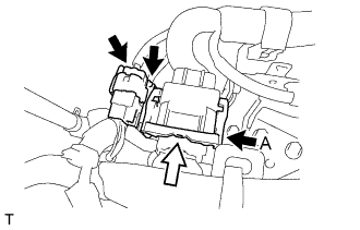 |
Connect the 3 connectors.
Engage the 4 wire harness clamps.
Install the ground cable to the automatic transmission assembly with the bolt
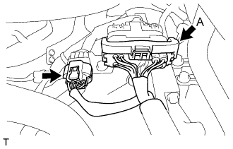 |
Connect the 2 connectors.
| 18. INSTALL STARTER ASSEMBLY |
| 19. INSTALL FRONT STABILIZER BAR |
| 20. INSTALL PROPELLER WITH CENTER BEARING SHAFT ASSEMBLY |
| 21. INSTALL REAR ENGINE UNDER COVER LH (w/ Floor Under Cover) |
Install the rear engine under cover LH with the 3 bolts and 8 clips.
| 22. INSTALL REAR ENGINE UNDER COVER RH (w/ Floor Under Cover) |
| 23. INSTALL NO. 2 ENGINE UNDER COVER |
Install the 7 bolts and the No. 2 engine under cover.
| 24. INSTALL NO. 1 ENGINE UNDER COVER |
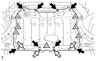 |
Install the No. 1 engine under cover with the 12 bolts and engage the 7 clips.
| Bolt A |
| Bolt B |
| 25. CONNECT BATTERY NEGATIVE TERMINAL |
| 26. ADD ENGINE COOLANT |
| 27. ADD AUTOMATIC TRANSMISSION FLUID |
| 28. CHECK FOR ENGINE COOLANT LEAKS |
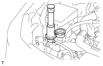 |
Fill the radiator with coolant and attach a radiator cap tester.
Warm up the engine.
Using a radiator cap tester, increase the pressure inside the radiator to 137 kPa (1.4 kgf/cm2, 20 psi), and check that the pressure does not drop.
If the pressure drops, check the hoses, radiator and water pump for leaks. If no external leaks are found, check the heater core, cylinder block and cylinder head.
| 29. INSPECT SHIFT LEVER POSITION |
When moving the shift lever from P to R with the ignition switch to ON and the brake pedal depressed, make sure that it moves smoothly and correctly into position.
Check that the shift lever does not stop when moving the shift lever from R to P, and check that the shift lever does not stick when moving the shift lever from D to M.
Start the engine and make sure that the vehicle moves forward after moving the shift lever from N to D and moves rearward after moving the shift lever to R.
If the operation cannot be performed as specified, inspect the park/neutral position switch assembly and check the shift lock control unit assembly installation condition.
| 30. CHECK FOR EXHAUST GAS LEAKS |
If gas is leaking, tighten the areas necessary to stop the leak. Replace the damaged parts as necessary.
| 31. RESET CHECK RESET MEMORY |