 |
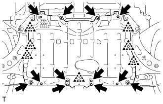
Disengage the 7 clips and remove the 12 bolts and No. 1 engine under cover.
AUTOMATIC TRANSMISSION ASSEMBLY > REMOVAL |
| 1. DISCONNECT CABLE FROM NEGATIVE BATTERY TERMINAL |
| 2. REMOVE NO. 1 ENGINE UNDER COVER |
|
Disengage the 7 clips and remove the 12 bolts and No. 1 engine under cover.
| 3. REMOVE NO. 2 ENGINE UNDER COVER |
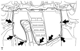 |
Remove the 7 bolts and the No. 2 engine under cover.
| 4. REMOVE REAR ENGINE UNDER COVER LH (w/ Floor Under Cover) |
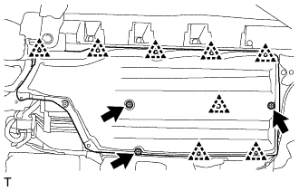 |
Remove the 3 bolts and 8 clips, then remove the rear engine under cover LH.
| 5. REMOVE REAR ENGINE UNDER COVER RH (w/ Floor Under Cover) |
| 6. DRAIN AUTOMATIC TRANSMISSION FLUID |
Remove the drain plug and gasket, and drain the ATF.
Install the drain plug and a new gasket.
| 7. REMOVE PROPELLER WITH CENTER BEARING SHAFT ASSEMBLY |
| 8. REMOVE FRONT STABILIZER BAR |
| 9. REMOVE STARTER ASSEMBLY |
| 10. DISCONNECT WIRING HARNESS CONNECTOR |
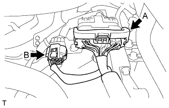 |
Release the lock of connector (A) and disconnect the connector.
Disconnect the connector (B).
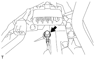 |
Remove the bolt and disconnect the ground cable.
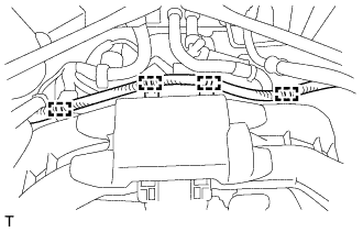 |
Disengage the 4 wire harness clamps.
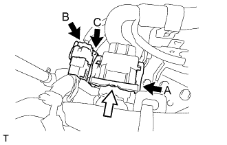 |
Release the lock of connector (A) and disconnect the connector.
Disconnect the connector (B) and (C).
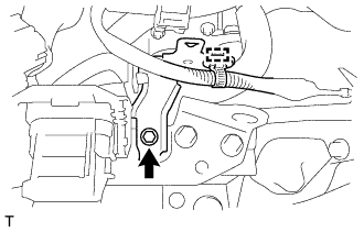 |
Disengage the wire harness clamp.
Remove the bolt and the wire harness clamp bracket.
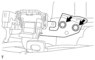 |
Remove the 2 bolts and the No. 2 engine hanger.
| 11. DISCONNECT VACUUM TUBE CONNECTOR HOSE (for LHD) |
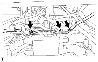 |
Remove the 2 bolts and the disconnect the union to check valve hose.
| 12. REMOVE FLYWHEEL HOUSING UNDER COVER |
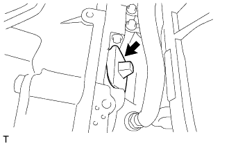 |
Remove the flywheel housing side cover from the automatic transmission assembly.
| 13. REMOVE DRIVE PLATE AND TORQUE CONVERTER SETTING BOLT |
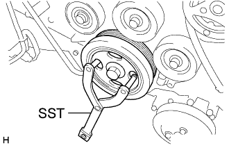 |
Using SST, hold the crankshaft pulley.
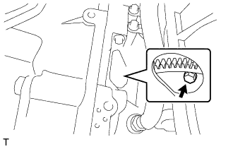 |
Remove the 6 drive plate and torque converter setting bolt.
| 14. DISCONNECT AUTOMATIC TRANSMISSION ASSEMBLY |
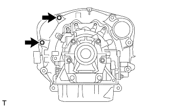 |
Remove the 2 bolts from the automatic transmission assembly.
| 15. REMOVE EXHAUST MANIFOLD |
| 16. SUSPEND ENGINE ASSEMBLY |
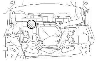 |
Support the engine assembly with an engine lifter so that it is stable shown in the illustration.
 | Attachment Placement Positions |
| 17. REMOVE TRANSMISSION OIL COOLER HOSE |
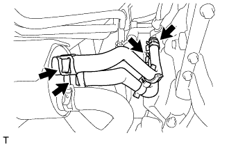 |
Loosen the 4 hose clamps and remove the 2 transmission oil cooler hoses.
| 18. SEPARATE OIL COOLER TUBE |
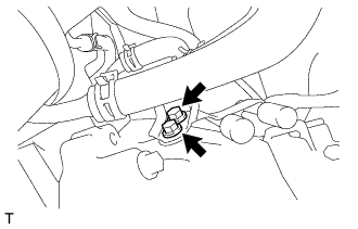 |
Remove the 2 bolts and separate the oil cooler tube.
| 19. REMOVE TRANSMISSION REVOLUTION SENSOR (NT) |
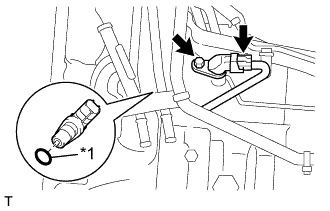 |
Disconnect the transmission revolution sensor connector.
| *1 | O-ring |
Remove the bolt and the transmission revolution sensor (NT).
Remove the O-ring from the transmission revolution sensor (NT).
| 20. REMOVE FLOOR SHIFT GEAR SHIFTING ROD SUB-ASSEMBLY |
While pushing the shift lock release button, move the shift lever to N.
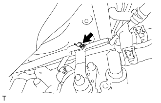 |
Remove the clip, pin and the floor shift gear shifting rod sub-assembly from the transmission control shaft lever RH.
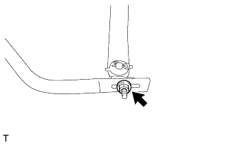 |
Remove the nut and disconnect the floor shift gear shifting rod sub-assembly.
| 21. REMOVE EXHAUST PIPE BRACKET |
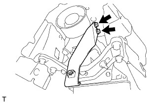 |
Remove the 2 bolts and the exhaust pipe bracket from the automatic transmission assembly.
| 22. SUPPORT AUTOMATIC TRANSMISSION ASSEMBLY |
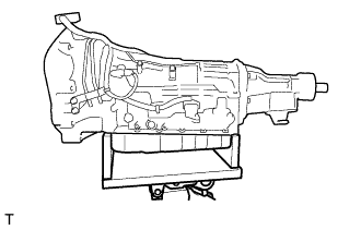 |
Support the automatic transmission assembly with a high transmission jack.
| 23. REMOVE REAR NO. 2 ENGINE MOUNTING INSULATOR |
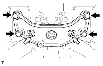 |
Remove the 4 bolts, 2 washers and 2 nuts and the rear No. 2 engine mounting insulator from the rear No. 1 engine mounting insulator.
 | Bolt |
 | Nut |
| 24. REMOVE REAR NO. 1 ENGINE MOUNTING INSULATOR |
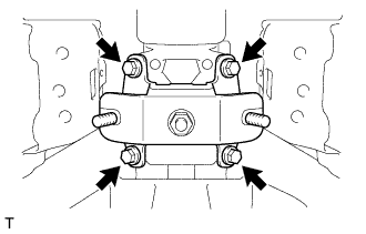 |
Remove the 4 bolts and the rear No. 1 engine mounting insulator from the automatic transmission assembly.
| 25. REMOVE AUTOMATIC TRANSMISSION ASSEMBLY |
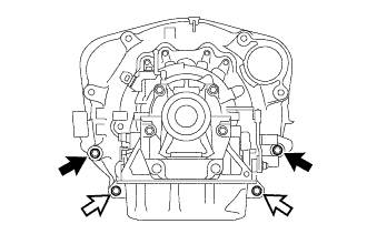 |
Remove the 2 bolts and 2 nuts and the automatic transmission assembly from the engine assembly.
| Bolt |
| Nut |
| 26. DISCONNECT WIRE HARNESS |
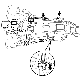 |
Disconnect the park/neutral position switch connector, transmission wire connector and the transmission revolution sensor connector.
Disengage the 6 wire harness clamps and the wire harness from the automatic transmission assembly.
| 27. REMOVE OIL COOLER TUBE |
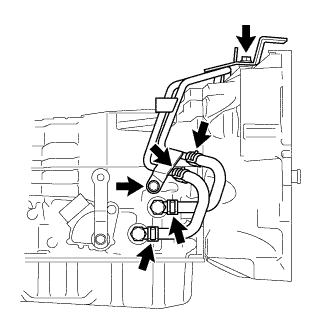 |
Loosen the 4 hose clamps and remove the 2 oil cooler hoses.
Remove the 2 bolts and the oil cooler tube from the automatic transmission assembly.
| 28. REMOVE TORQUE CONVERTER ASSEMBLY |
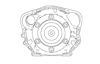 |
Remove the torque converter assembly from the automatic transmission assembly.
| 29. INSPECT TORQUE CONVERTER ASSEMBLY |
Inspect the one-way clutch.
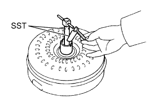 |
Install SST into the inner race of the one-way clutch.
Set SST so that it fits in the notch of the torque converter hub and the outer race of the one-way clutch.
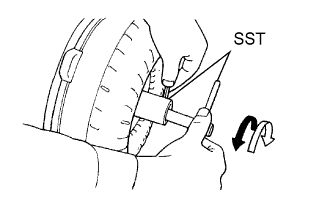 |
With the torque converter assembly standing on its side, check that the clutch locks when SST is turned counterclockwise and rotates freely and smoothly when SST is turned clockwise.
| Lock |
| Free |
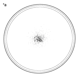 |
Determine the condition of the torque converter assembly.
| *a | Sample showing maximum allowable amount of powder in ATF |
Check that the following conditions are met:
Replace the ATF in the torque converter assembly.
If the ATF is discolored and/or has a foul odor, stir the ATF in the torque converter assembly thoroughly and drain the ATF with the torque converter assembly facing upward.
Clean and check the transmission oil cooler.
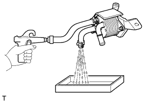 |
If the torque converter assembly is inspected or the ATF is replaced, clean the transmission oil cooler.
If the ATF is cloudy, inspect the transmission oil cooler.
 |
Prevent deformation of the torque converter assembly and damage to the oil pump gear.
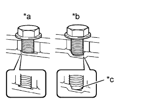
| *a | Correct |
| *b | Incorrect |
| *c | Bottom is damaged |
When any marks due to interference are found on the end of a bolt for the torque converter assembly and on the bottom of the bolt hole, replace the bolt and torque converter assembly.
Make sure all of the bolts are the same length.
Make sure no spring washers are missing.