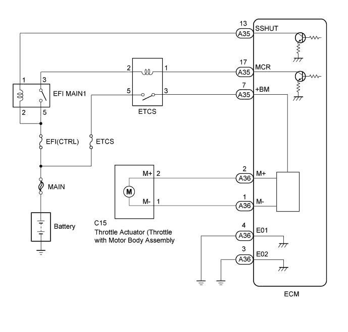
DTC P2101 Throttle Actuator Control Motor Circuit Range/Performance |
DTC P2102 Throttle Actuator Control Motor Circuit Low |
DTC P2103 Throttle Actuator Control Motor Circuit High |
| DTC No. | DTC Detection Condition | Trouble Area |
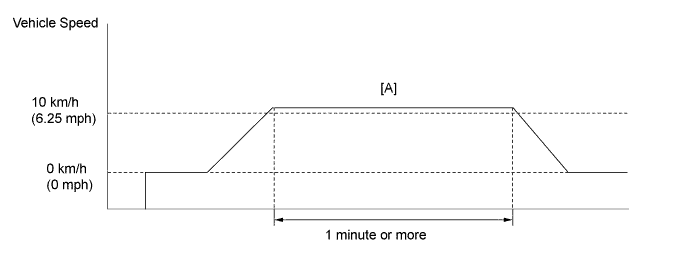
| P2101 | One of the following conditions is met (1 trip detection logic):
|
|
| P2102 | ECM is turning ETCS relay on but throttle actuator power supply voltage is 5 V or less. (1 trip detection logic) |
|
| P2103 | ECM is turning ETCS relay off but throttle actuator power supply voltage is 5 V or more. (1 trip detection logic) |
|

| GTS Display | Description |
| NORMAL |
|
| ABNORMAL |
|
| INCOMPLETE |
|
| N/A |
|

| 1.INSPECT TERMINAL VOLTAGE (POWER SOURCE OF THROTTLE WITH MOTOR BODY ASSEMBLY) |
![]() |
Measure the voltage according to the value(s) in the table below.
| Tester Connection | Switch Condition | Specified Condition |
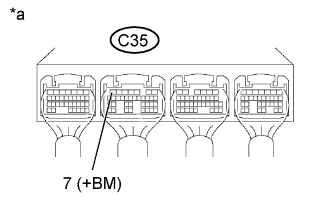
| C35-7 (+BM) - Body ground | Ignition switch ON | 11 to 14 V |
| *a | Component with harness connected (ECM) |
|
| ||||
| OK | |
| 2.INSPECT THROTTLE WITH MOTOR BODY ASSEMBLY (RESISTANCE OF THROTTLE ACTUATOR) |
Inspect the throttle with motor body assembly (Click here).
|
| ||||
| OK | |
| 3.CHECK HARNESS AND CONNECTOR (THROTTLE WITH MOTOR BODY ASSEMBLY - ECM) |
Disconnect the throttle with motor body assembly connector.
Disconnect the ECM connector.
Measure the resistance according to the value(s) in the table below.
| Tester Connection | Condition | Specified Condition |
| C15-2 (M+) - A36-2 (M+) | Always | Below 1 Ω |
| C15-1 (M-) - A36-1 (M-) | Always | Below 1 Ω |
| Tester Connection | Condition | Specified Condition |
| C15-2 (M+) or A36-2 (M+) - Body ground | Always | 10 kΩ or higher |
| C15-1 (M-) or A36-1 (M-) - Body ground | Always | 10 kΩ or higher |
|
| ||||
| OK | |
| 4.INSPECT THROTTLE WITH MOTOR BODY ASSEMBLY (VISUALLY CHECK THROTTLE VALVE) |
Check for foreign objects between the throttle valve and the housing.
|
| ||||
| OK | |
| 5.INSPECT THROTTLE WITH MOTOR BODY ASSEMBLY (THROTTLE VALVE) |
Check if the throttle valve opens and closes smoothly.
|
| ||||
| OK | ||
| ||
| 6.INSPECT RELAY (ETCS) |
Inspect the ETCS relay .
|
| ||||
| OK | |
| 7.CHECK HARNESS AND CONNECTOR (ETCS RELAY - EFI MAIN1 RELAY - BATTERY) |
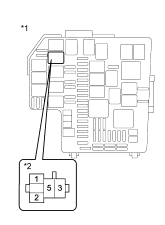
![]() |
Remove the ETCS relay from the engine room relay block assembly.
Measure the voltage according to the value(s) in the table below.
| Tester Connection | Condition | Specified Condition |
| 5 (ETCS relay holder) - Body ground | Always | 11 to 14 V |
| 2 (ETCS relay holder) - Body ground | Ignition switch ON | 11 to 14 V |
| Result | Proceed to |
| Normal | A |
| ETCS relay terminal 5 is abnormal. | B |
| ETCS relay terminal 2 is abnormal. | C |
| *1 | Engine room relay block assembly |
| *2 | ETCS relay terminal |
|
| ||||
|
| ||||
| A | |
| 8.CHECK HARNESS AND CONNECTOR (ECM - ETCS RELAY) |
Disconnect the ECM connector.
Remove the ETCS relay from the engine room relay block assembly.
Measure the resistance according to the value(s) in the table below.
| Tester Connection | Condition | Specified Condition |
| A35-17 (MCR) - ETCS relay terminal 1 | Always | Below 1 Ω |
| A35-7 (+BM) - ETCS relay terminal 3 | Always | Below 1 Ω |
| Tester Connection | Condition | Specified Condition |
| A35-17 (MCR) or ETCS relay terminal 1 - Body ground | Always | 10 kΩ or higher |
| A35-7 (+BM) or ETCS relay terminal 3 - Body ground | Always | 10 kΩ or higher |
|
| ||||
| OK | |
| 9.INSPECT RELAY (EFI MAIN1) |
Inspect EFI MAIN1 relay .
|
| ||||
| OK | |
| 10.CHECK HARNESS AND CONNECTOR (ETCS RELAY - EFI MAIN1 RELAY) |
Remove the ETCS relay from the engine room relay block assembly.
Remove the EFI MAIN1 relay from the engine room relay block assembly.
Measure the resistance according to the value(s) in the table below.
| Tester Connection | Condition | Specified Condition |
| ETCS relay terminal 2 - EFI MAIN1 relay terminal 3 | Always | Below 1 Ω |
| Tester Connection | Condition | Specified Condition |
| ETCS relay terminal 2 or EFI MAIN1 relay terminal 3 - Body ground | Always | 10 kΩ or higher |
|
| ||||
| OK | ||
| ||