Home › Drivetrain · TX6A AUTOMATIC TRANSMISSION / TRANSAXLE › AUTOMATIC TRANSMISSION SYSTEM

DTC    P2719    Pressure Control Solenoid "D" Circuit Performance (SLT Solenoid)

DTC    P2720    Pressure Control Solenoid "D" Control Circuit Low

DTC    P2721    Pressure Control Solenoid "D" Control Circuit High

for Preparation Click here


DESCRIPTION

The shift solenoid valve SLT is controlled by the duty ratio as determined in advance by the transmission control computer, based upon signals from the accelerator position sensor, input speed sensor NT and output speed sensor SP2. In this way, the line pressure is adjusted to match the throttle valve opening angle and engine output. The TCM uses the revolution signals from the input speed sensor NT and output speed sensor SP2 to detect clutch and other slipping.

DTC No.
DTC Detection Condition
  1. Diagnosis Condition
  2. Malfunction Status
  3. Malfunction Time
  4. Other
Trouble Area
P2719
  1. Not learning control prohibited status
  2. The difference between the shift solenoid valve SLT operational specified current and operational feedback current is 12 A or more in total.
  3. Detects "2.Malfunction Status" 2 times consecutively.
  4. 1-trip detection logic
  1. Shift solenoid valve SLT
  2. Transmission wire
  3. Harness and connector
  4. TCM
P2720
  1. Not learning control prohibited status
  2. 1 second or more has elapsed after turning shift solenoid valve SLT off.
    The shift solenoid valve SLT operational feedback voltage is 0.018 V or less.
  3. Detects malfunction that continues for 100 ms or more 5 times consecutively.
  4. 1-trip detection logic
  1. Shift solenoid valve SLT
  2. Transmission wire
  3. Harness and connector
  4. TCM
P2721
  1. Not learning control prohibited status
  2. 1 second or more has elapsed after turning shift solenoid valve SLT on.
    The shift solenoid valve SLT operational feedback voltage is 0.257 V or more.
  3. Detects malfunction that continues for 100 ms or more 5 times consecutively.
  4. 1-trip detection logic
  1. Shift solenoid valve SLT
  2. Transmission wire
  3. Harness and connector
  4. TCM

MONITOR DESCRIPTION

When an open or short in the shift solenoid valve SLT circuit or feedback stuck is detected, the TCM interprets this as a fault. The TCM will turn on the MIL and store the DTC.

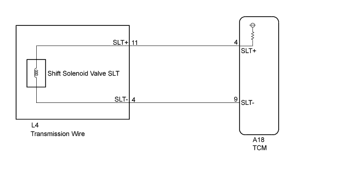
WIRING DIAGRAM


C250701E03


INSPECTION PROCEDURE

NOTICE:
Perform the universal trip to clear permanent DTCs (Click here).

1.CHECK HARNESS AND CONNECTOR
  1. Disconnect the A18 TCM connector.

  1. Measure the resistance according to the value(s) in the table below.

    Standard resistance:
    Tester Connection
    Condition
    Specified Condition
    A18-4(SLT+) - A18-9(SLT-)
    20°C(68°F)
    5.0 to 5.6 Ω

  1. Disconnect the A18 TCM connector.


NG
Go to step 3
OK


2.REPLACE TCM
  1. Replace the TCM (Click here).


NEXT

PERFORM THE RESET MEMORY (Click here)  

3.CHECK HARNESS AND CONNECTOR (TRANSMISSION WIRE - TCM)
  1. Disconnect the A18 TCM connector.

  1. Disconnect the L4 transmission wire connector.

  1. Measure the resistance according to the value(s) in the table below.

    Standard resistance:
    Tester Connection
    Condition
    Specified Condition
    A18-4(SLT+) - L4-11(SLT+)
    Always
    Below 1 Ω
    A18-9(SLT-) - L4-4(SLT-)
    Always
    Below 1 Ω

  1. Measure the voltage according to the value(s) in the table below.

    Standard voltage:
    Tester Connection
    Condition
    Specified Condition
    A18-4(SLT+) - Body ground
    Ignition switch ON
    Below 1 V
    A18-9(SLT-) - Body ground
    Ignition switch ON
    Below 1 V

  1. Connect the A18 TCM connector.

  1. Connect the L4 transmission wire connector.


NG
REPAIR OR REPLACE HARNESS OR CONNECTOR
OK


4.INSPECT SHIFT SOLENOID VALVE SLT
  1. Remove the shift solenoid valve SLT (Click here).

  1. Perform inspection of the shift solenoid valve SLT .


NG
REPLACE SHIFT SOLENOID VALVE SLT (Click here)
OK

REPAIR OR REPLACE TRANSMISSION WIRE (Click here)