Home › Engine / Hybrid System › CRUISE CONTROL › CRUISE CONTROL SYSTEM

CRUISE CONTROL SYSTEM > Clutch Switch Circuit

for Preparation Click here


DESCRIPTION

Clutch switch circuit inspection is necessary for M/T vehicles.
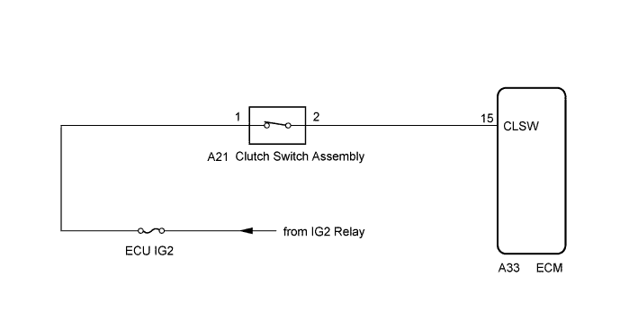
When the clutch pedal is released, the ECM receives positive (+) battery voltage through the ECU IG2 fuse. While depressing the clutch pedal, the clutch switch sends a signal to terminal CLSW of the ECM. The ECM cancels cruise control drive when terminal CLSW receives the signal.

WIRING DIAGRAM


A280664E01


INSPECTION PROCEDURE

HINT:
Clutch switch assembly conditions can be checked using the GTS.
  1. Connect the GTS to the DLC3.
  2. Turn the ignition switch to ON.
  3. Turn the GTS on.
  4. Enter the following menus: Powertrain / Engine / Data List / All Data / Clutch Switch (Click here).

    Engine 
    Clutch Pedal Operation
    Clutch Switch
    Depressed
    ON
    Released
    OFF

1.CHECK ECM (TERMINAL VOLTAGE)


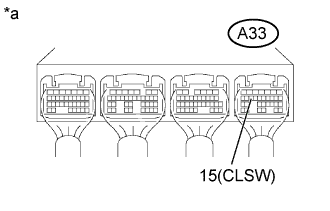
    A280163E01
  1. Turn the ignition switch to ON.

  1. Measure the voltage according to the value(s) in the table below.

    Standard voltage:
    Tester Connection
    Condition
    Specified Condition
    A33-15 (CLSW) - Body ground
    Clutch pedal depressed
    Below 1 V
    Clutch pedal released
    11 to 14 V

    Text in Illustration 
    *a
    Component with harness connected
    (ECM)


NG
Go to step 2
OK

PROCEED TO NEXT SUSPECTED AREA SHOWN IN PROBLEM SYMPTOMS TABLE (Click here)  

2.INSPECT CLUTCH SWITCH ASSEMBLY
  1. Inspect the clutch switch assembly (for LHD) .

  1. Inspect the clutch switch assembly (for RHD) .


Result:

Result
Proceed to
OK
A
NG (for LHD)
B
NG (for RHD)
C


B
REPLACE CLUTCH SWITCH ASSEMBLY (Click here)

C
REPLACE CLUTCH SWITCH ASSEMBLY (Click here)
A


3.CHECK HARNESS AND CONNECTOR (ECM - CLUTCH SWITCH ASSEMBLY)
  1. Disconnect the clutch switch assembly connector.

  1. Disconnect the ECM connector.

  1. Measure the resistance according to the value(s) in the table below.

    Standard resistance (Check for open):

    Tester Connection
    Condition
    Specified Condition
    A33-15 (CLSW) - A21-2
    Always
    Below 1 Ω


    Standard resistance (Check for short):

    Tester Connection
    Condition
    Specified Condition
    A33-15 (CLSW) or A21-2 - Body ground
    Always
    10 kΩ or higher


NG
REPAIR OR REPLACE HARNESS OR CONNECTOR (ECM - CLUTCH SWITCH ASSEMBLY)
OK

INSPECT ECM POWER SOURCE CIRCUIT (Click here)